**Abstract:** This paper presents a method for generating process plans in CAPP (Computer-Aided Process Planning). The process generation for parts is essentially a reverse reasoning approach, starting from the final part and working backward to determine the blank. It creates a processing chain for each surface element, and by analyzing and reconstructing this chain, the machining technology for the part is developed.
**Keywords:** CAD, CAPP, surface features
In every aspect of CAPP, it is essential to extract information from CAD systems to generate process documentation. This involves several key tasks: determining the machining method, arranging the sequence of operations, calculating dimensional chains, selecting tools and measuring instruments, choosing machine tools, deciding on fixtures, and designing the blank. A successful CAPP system must focus on improving these aspects. In this paper, a process chain generation and recombination method is effectively applied to produce the machining plan for rotating body parts.
**First, the overall structure of the system**
The system begins by converting CAD data into a format that CAPP can use, enabling seamless integration between CAD and CAPP. This eliminates the need for redundant data entry. The system then preprocesses the data, organizing various surface elements. Based on the machining requirements of each surface element—such as accuracy and surface roughness—the system generates a processing chain. After disassembling the chain, it reorganizes the machining steps to form the complete process plan. The block diagram of the system is shown in Figure 1.
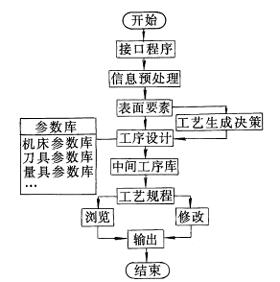
The system uses a modular design, including modules for information interface, process generation, and system maintenance. This design allows for easy addition and modification of functions. Within the process generation module, libraries such as surface features, machining allowances, machine tool parameters, and tool parameters are well-organized during development, providing a solid foundation for future expansion to non-rotating parts.
**Second, the process generation method**
In the design of CAPP, producing process documents is one of the most critical tasks. This includes designing the blank, setting up the machining sequence, determining process dimensions, selecting machine tools, and choosing tools and measuring devices. Each of these aspects is handled through separate modules. The key lies in generating different processing chains based on surface features and using logical judgment from other modules to finalize the production process.
**1. Routing decision**
The processing chain is determined based on the surface features of the part. Factors like machining accuracy, surface roughness, heat treatment conditions, batch size, and the form of the blank influence the outcome. For example, if a surface is cylindrical with an accuracy of ≤ IT7 or a surface roughness of ≤ 1.6 μm, the final machining step is grinding, following a sequence like rough turning → finish turning → grinding. The grinding allowance is calculated from the machining allowance database, and the size before grinding is derived accordingly.
In Figure 2, the shaft has five surface elements, with elements 1, 3, 4, and 5 being primary, and element 2 being auxiliary. The system generates a processing chain for each surface element, and based on the analysis, the chains are displayed in Table 1.
From Table 1, the processing chain for surface element 1 (outer circle) includes roughing, finishing, and grinding. The system decomposes and organizes these chains, grouping similar steps together. For instance, all roughing steps are combined into one operation. For a two-step rotating part, the system determines which end to clamp first based on the largest diameter, and then proceeds to the other side. The sequence of operations is determined logically, ensuring proper order according to standard principles like "coarse first, fine later."
Heat treatment steps are automatically inserted based on the technical requirements of the part. Whether it's preliminary, intermediate, or final heat treatment, the system places it in the appropriate position. The concentration or dispersion of processes depends on the production volume, accuracy, and complexity of the part.
In this example, the final process sequence (excluding heat treatment) is: Rough Turning → Finish Turning → Milling → Grooving.
**2. Determination of steps**
Each step in the process corresponds to the machining of a specific surface. For example, when grinding the outer circle, the finished dimension is known, and the previous size can be calculated based on the machining allowance. This helps in determining the exact dimensions at each stage.
**3. Selection of machine tools**
Machine tool specifications and accuracy levels are stored in a database within the system. Based on the machining method, required accuracy, and dimensions of the surface elements, the system automatically selects the appropriate machine tool. For example, the choice of a lathe depends on factors such as the maximum diameter of the part, its total length, and whether it’s for rough or finish machining.
**4. Selection of process equipment**
Tools, gauges, and fixtures are selected through the system’s decision logic, which searches the corresponding libraries to find matching components and determine the best fit.
**Third, the system design requirements**
The system requires a computer with a CPU above 486, 16MB of memory, and a Windows environment. It was developed using Visual C++, and the database is managed using Visual FoxPro. The modular design makes it easy to add, remove, or modify functions, enhancing system maintainability. The database also supports modification, printing, reporting, and querying, allowing real-time updates based on production needs.
**Fourth, the conclusion**
By organizing part information into surface elements and automatically generating their processing chains, the system successfully creates the machining process. Through analysis, reconstruction, and combination of the chains, the entire process is efficiently generated, demonstrating the effectiveness of the proposed method.
Mini Air Cylinder,Mini Air Cylinder Pneumatic,Airtac Mini Cylinder,Mini Pneumatic Air Cylinder
ShinYee (Zhejiang) Pneumatic Technology Co., LTD , https://www.pneuvalve.com