Diesel Generator | Diesel Generator Price / 2018-09-01
Diesel generators
Common adjustment and maintenance method for diesel engine and gasoline engine of generator set
1. Adjustment of valve clearance
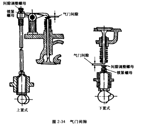
There are two types of valve clearance: upper and lower, as shown in Figure 2-34. The valve clearance is usually checked and adjusted in the cold state. The valve clearance of diesel engines and gasoline engines is specified in the instruction manual. Check and adjust the valve clearance as follows:
(1) Rotate the crankshaft so that the valve of the first cylinder is completely closed and the tappet is at the lowest position.
(2) Measure the clearance between the end face of the valve stem and the rocker arm (the side between the valve end face and the tappet ) with a plug gauge corresponding to the thickness of the valve .
(3) When the clearance is not satisfactory, loosen the lock nut, turn the adjustment nut with a screwdriver or a wrench, and screw in or out to increase or decrease the clearance. It is suitable to measure with the plug gauge when adjusting, and it is appropriate to take out the plug gauge and feel a little resistance.
(4 After adjusting, tighten the lock nut and check again if the gap changes. If there is any change, readjust it.
(5) According to the above method, turn the crankshaft again, and check and adjust the valve clearance of other cylinders one by one according to the working order of each cylinder.
The valve clearance can also be adjusted twice as follows (take the 4135 or 4110 diesel engine as an example): Turn the crankshaft so that the pointer on the flywheel cover inspection window is aligned with the timing zero line on the flywheel. At this time, the first and fourth cylinder pistons are located. Top dead center. Then turn the crankshaft slightly to observe whether the intake and exhaust valves of the first cylinder are in the closed state. When it is determined that the first cylinder is in the compression stroke and the piston is at the top dead center, the intake and exhaust of the first cylinder can be adjusted. Door clearance, intake valve clearance of the second cylinder, and exhaust valve clearance of the third cylinder. Then the crankshaft is rotated 360°, so that the fourth cylinder is in the compression stroke, the piston is at the top dead center, then the exhaust valve clearance of the second cylinder is adjusted, the intake valve clearance of the third cylinder, and the intake and exhaust of the fourth cylinder Door clearance.
2. Adjustment of diesel engine injection time
After the diesel engine has been disassembled or operated for a certain period of time (usually 500 hours), the injection time (oil supply advance angle) must be checked and adjusted. The injection time refers to the angular position of the crankshaft before the top dead center of the compression stroke of the piston when the oil pump is close to the oil outlet, and does not refer to the angle at which the injector starts to spray into the cylinder. If the injection time is too early, the diesel engine will be knocked, the idle speed will be unstable, and the power will drop. If the injection time is too late, it will cause difficulty in starting, the exhaust will emit black smoke, and the power will be insufficient.
The inspection and adjustment method of the injection time of the 4135 diesel engine is as follows: first remove the high pressure oil pipe of the first cylinder sub-pump, rotate the crankshaft, aim the flywheel cover monitoring hole pointer to the fixed zero line on the flywheel, and make the first cylinder piston Compress the top dead center of the stroke, then reverse the crankshaft by about 40°, and then slowly turn it forward. At the same time, pay attention to the change of the oil level in the outlet valve seat. When the oil surface just fluctuates, it means the first cylinder starts. Spraying oil. At this time, the fixed time line on the high-pressure oil pump coupling should be aligned with the fixed time line on the high-pressure oil pump shaft cover. According to the scale of the flywheel pointed by the pointer on the flywheel cover inspection hole, the injection time can be determined . This time should be 28°~31° before the top dead center . If the gauge is not met, loosen the two screws on the coupling plate and slowly rotate the crankshaft to make the coupling plate rotate through a certain angle (the indexing line is engraved on the coupling plate, 3° per grid ) , then tighten the two screws and check again. If it still does not meet the requirements, continue to adjust as described above. 5°。 When the oil supply time of the second cylinder is adjusted, the inspection and adjustment shall be carried out according to the working order of the cylinders of the diesel engine .
3. Gasoline engine ignition timing adjustment
Premature ignition and too late ignition time will have adverse consequences for the operation of the gasoline engine, and should be checked and adjusted in time. When the distributor assembly is repaired or overhauled, the ignition timing must be recalibrated when the gasoline engine is replaced.
(1) First remove the high-voltage line of the first cylinder spark plug and make it 3 ~4mm away from the cylinder block , then turn on the ignition switch and shake the crankshaft. When the first cylinder high voltage line jumps, stop rotating the crankshaft, and check whether the ignition timing mark is aligned. If the timing mark on the flywheel deviates significantly from the score line on the flywheel cover, the ignition timing should be adjusted.
(2) When adjusting the ignition timing, first loosen the random splint fixing screw, and then insert the distributor into the cylinder block. At this time, the octane regulator is adjusted to the “0†position.
(3) Use a socket wrench to remove the spark plug of the first cylinder, use your fingers to block the spark plug hole on the cylinder head, turn the crankshaft, and when you feel the top force and hear the sound of the air, slowly turn the crankshaft to make the piston Reach the top dead center. There are many ways to determine the top dead center. For example, if the timing mark on the flywheel is opposite to the reticle or pointer of the flywheel cover, it is the end of compression and the piston reaches the top dead center. When the mark cannot be determined, a wire is inserted into the cylinder, and the crankshaft is slowly rotated, and the feeling is used to judge whether the piston reaches the top dead center.
(4) After the piston reaches the top dead center, unplug the central high-voltage power cord of the distributor, and make its end at 3 ~4mm of the cylinder , turn on the ignition switch, and then rotate the distributor housing in the direction of the rotation of the distributor shaft. Close the contacts . Rotate the housing again, until the end of the central high-voltage plug-in has a spark skip, when the contact just opens.
(5) Tighten the fixing screws of the plate clamp to fix the distributor, install the splitter head, distributor cap, and install the spark plug.
(6) Insert the high-voltage line of each cylinder in the direction of rotation of the fire head in the order of ignition of the gasoline engine.
Although the above-mentioned ignition timing correction is performed, whether the correction is appropriate or not is checked in normal operation and further adjustment is necessary if necessary. For example, after the gasoline engine reaches the normal temperature, the throttle is suddenly increased. The rotation speed of the gasoline engine cannot be increased, and it feels "boring", indicating that the ignition time is too late. The distributor housing should be rotated and adjusted in the opposite direction of the rotation of the burner. When the throttle is suddenly increased during operation, if there is a similar metal knocking sound of “嘎, 嘎â€, it means that the ignition time is too early, the housing should be rotated according to the direction of rotation of the burner, after repeated adjustment and operation for a period of time. until.
4. Adjustment and maintenance of diesel fuel injection pump
The adjustment and maintenance of the fuel injection pump is a meticulous and precise work. Keep the parts clean during disassembly and assembly, especially for some parts. They must be placed in pairs and cannot be disordered, because the parts are not interchangeable.
(1) Adjustment of injection quantity of fuel injection pump. Inspection and adjustment of the uniformity of fuel injection is best carried out on a dedicated test bench. When there is no such device, it can be checked and adjusted by simple hand cranking: the fuel pump is stuck on the vise. Make a hand crank and attach it to the connection plate of the fuel injection pump. Connect the tubing, fuel injector and fuel tank. Shake the handle and drain the air from the oil passage. Put a cup with scale in the discharge port of each injector. Move the adjustment rack to each of the oil supply stations specified by the manufacturer . Turn the hand crank for not less than 100 turns, then check the amount of oil collected in the oil cup and calculate the percentage difference between the oil supply of each pump. Generally , the difference in fuel injection at low speed should be less than 8%~10%. Otherwise, adjustment should be made. When the adjustment cannot be made, the fuel injection pump should be replaced.
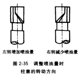
When the fuel injection amount is not evenly adjusted, the adjustment rack can be moved to the position where the oil supply is stopped. Use a small screwdriver to loosen the locking screw on the adjusting gear and then touch the small screwdriver to touch the oil in the small hole of the control sleeve. Use a small hand hammer to gently tap the screwdriver handle. If the fuel injection amount is too small, make the control sleeve The cylinder is turned to the left by a certain angle; the injection is the most excessive, so that the control sleeve is turned to the right by a certain angle. Rotation control sleeve to adjust the injection amount hours should be configured according to the determined direction of rotation, shown in Figure 2-35. After the adjustment is completed , the test is carried out for re-inspection, and the fuel injection amount of each cylinder should be close to the same.
Generally, when reassembling, pull the adjusting rack to the position of the maximum oil supply, adjust the slot center line at the gear locking screw and the center line of the control sleeve and the plunger lug and the pump body top hole the center line in a straight line, and facing the pump body, a plunger cylinder are a few samples, which basically suitable amount of oil.
(1) Maintenance of the oil delivery valve
1 The oil discharge valve spring should be replaced. The oil discharge valve has dirt, so that the sealing surface is not tightly sealed , and it can be cleaned and cleaned and then used.
2 The oil discharge valve is not tightly sealed due to wear and can be ground to improve the sealing. The surface can be placed on the drill bit holder and coated with a small amount of chrome oxide and engine oil (note that the valve sand is not available), the drill bed is opened in the slowest position, and the valve seat is ground. When grinding, it should be noted that the abrasive must be applied to the slope of the oil discharge valve, and should not be applied too much to avoid wear and tear in the place where it should not be worn. After grinding, clean it with gasoline. The ground surface should be free of grooves and arcs and tightly sealed. The pressure oil valve ring if severe abrasion, the surface is not glossy, black, look carefully pull marks, replace the outlet valve member.
3 The sealing device of the oil discharge valve, such as the high pressure oil seal copper gasket on the top surface of the valve body, should be replaced. Low pressure tight seal seat outer rubber ring is damaged, it should also be replaced. When installing the oil discharge valve, the joint tightening torque should be (80±0.5) N • m (according to the value in the manual), the torque should not be too large, so as to avoid the deformation of the plunger sleeve and affect the plunger freedom. mobile.
(2) Overhaul of the plunger. The plunger is bitten with dirt and can be cleaned and assembled with clean gasoline. If the plunger coupler is severely worn or strained, replace the coupling. During the inspection, the plunger can be pulled out 10~15mm, the plunger sleeve is simple, and the tilting is about 45°. The plunger should be able to sink to the bottom end of the sleeve with its own weight, and there should be no place anywhere. The phenomenon of blockage and jamming is acceptable, otherwise it should be repaired or replaced.
(3) Adjust the adjustment of the rack. Adjust the gear bar to ensure that it moves flexibly, and there must be no blockage. The reason for the blockage is that the clearance between the toothed rod and the bushing is too small, the plunger bites or the spring is broken, and the meshing gap between the toothed rod and the adjusting gear is too small. The cause should be found and excluded. If the toothed rod is too tightly fitted with the bushing, it can be reamed with a live reamer.
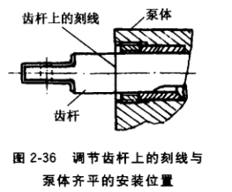
When adjusting the gear rod assembly, the tooth rod reticle should be flush with the pump, as shown in Figure 2-36. If the inward movement is too much and the engraved line is not visible, the maximum oil quantity is too large; if the outward movement is excessive, the maximum oil quantity is too small, and adjustment must be made.
5. Adjustment and maintenance of diesel injector
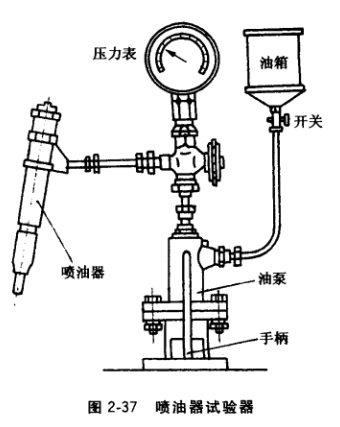
(1) Adjustment of the injector. When inspecting and adjusting the injector, it should be carried out on the tester, as shown in Figure 2-37. Connect the injector to the high pressure oil pipe of the tester. Pump oil with hand oil pump, when the injection pressure is (16.7±0.48) MPa , The fuel injection should begin. If it does not meet the requirements, the cap can be removed, the lock nut can be loosened, and the adjustment screw can be used to adjust the pressure of the pressure regulating spring to the ejector pin to achieve the normal injection pressure. If the pressure is not enough, the screw can be adjusted. If the pressure is too high, the adjusting screw can be screwed out. After adjustment, tighten the adjusting nut and install the cap.
After the injection pressure is adjusted, the injector seal should be checked. The oil is pumped by the hand oil pump to a pressure of 16 MPa, and then the hand pump is ignited at a uniform speed of 10 times per minute . When the pressure indicated by the pressure gauge is raised from 16 MPa to 17 MPa , the fuel injection starts. Heretofore, there should be no leakage and injector oil leakage phenomenon, but allow a trace amount of moisture. If the seal is not tight, remove the cleaning and grinding coupler or replace the coupler.
Good injector, spray test at a speed of 60~70 times per minute . The oil mist should be even and foggy. The fog beam should be evenly distributed in any section. The cone angle is 15°~20°. Drop oil, splash phenomenon. The fuel injection cut should be timely,
And there is a crisp sound of "å™—, å™—". The pressure of the injection pressure of the same diesel engine injector should not exceed 1 MPa - the injection pressure should be 15.5 - 17. 5MPa The injection pressure of the new machine is 16. 5~17. 5MPa (refer to the random manual).
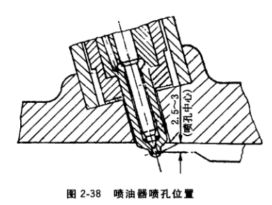
When the injector refitted into the cylinder, the cylinder gasket injector planar contact can not be thickened, the injector must remain extended cylinder head bottom plane 2. 5~3mm, as shown in Figure 2-38, in order to ensure good combustion of diesel, or will cause row of black smoke phenomenon, messy percussion in the diesel engine.
( 2) Maintenance of the injector. After the defective injector is removed and decomposed, it is placed in diesel or gasoline to soften the carbon deposit and clean it, and then check the condition of each component. If the ram is bent, it can be placed on the platform with a soft metal hammer to tap straight, and the spring should be replaced. The nozzle of the injector is blocked and can be penetrated by a steel wire with a diameter of 0.2 mm . If the nozzle hole is ground in an oval shape, it should be replaced. When inspecting, pay attention to the inspection of the guide surface of the needle valve and the valve seat and the sealing cone. If the surface is dark, there is a flaw, indicating that it is worn; the oil needle guiding surface is dark, which is the surface is heated. The scars left after (annealing) should be replaced with new ones.
6. Oil pump maintenance
Fuel pump failure can occur intermittently or not at all for the supply of oil, and therefore should be timely maintenance. For example, if the piston of the oil pump is worn seriously or the spring is broken, it should be replaced. It can be replaced by gasoline after being cleaned by oil. The plastic check valve is severely worn or skewed . When the valve seat is not tightly sealed, the check valve and the valve seat can be ground to restore the seal. The plastic check valve is not sealed because the sucked sand sticks to the plane of the valve . It can be placed on the oil stone for smoothing. When the check valve spring is broken, it should be replaced. If the rubber seal of the hand pump piston is seriously worn or damaged, it may cause air leakage, oil leakage or stop the oil supply. When the oil pump is used to pump oil, it feels relaxed and there is no suction. If the pump does not oil, the rubber should be replaced. Sealing ring. If the sealing ring is only worn and not damaged, in the case of lack of material, according to the width of the groove on the piston, a copper piece of about 0.10 mm thick (depending on the specific circumstances) should be cut into a circle and surrounded by the piston groove. Inside the ditch, put on the old rubber seal ring for reuse.
7. Adjustment and maintenance of gasoline engine vaporizer
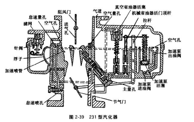
There are many forms of vaporizers, but their structure and working principle are basically the same. The following is an example of the use of the wider 231 carburetor shown in Figure 2-39 to illustrate the adjustment and maintenance of the carburetor.
( 1) Adjustment of the oil level of the float chamber and maintenance of the float. When inspecting the oil level of the float chamber, the screw plug of the vaporizer inspection hole should be removed first, so that the gasoline engine runs at an idle speed, and then the oil level is checked from the inspection hole. If the gasoline flows out from the inspection hole, the oil level is too high; If you can't see it, the face is too low; if you can see the gasoline, but the gasoline does not flow out is appropriate. When adjusting the oil level, the vaporizer float chamber cover can be removed and adjusted according to the form of the vaporizer, bending the tongue on the float arm or changing the thickness of the gasket under the needle seat. If the oil level is too high, the gasket should be added under the needle seat or the tongue on the float wall should be bent upwards. If the oil level is too low, it will be reversed.
The oil level is too high, sometimes due to the infiltration of the float into the gasoline, causing the weight of the float to increase. Remove the float when repairing, and shake it near the ear. If you hear a "squeaky, squeaky" sound inside , the float has broken and leaked. Place the float in the hot water tank , so that the gasoline in the float is evaporated by heat, emerges from the crack, and then marks the crack in order to weld. After the weld repair, the weight of the float increases and the oil level must be re-adjusted. The float has a recess, the solder inch with a wire welding, the flattened recess in the depressions, then remove the wire.
(2) Maintenance of the triangular needle valve and seat. When the gasoline engine was running, it suddenly smelled the smell of gasoline and felt the power was insufficient. It was found that there was a lot of gasoline spilling around the vaporizer. This kind of failure is probably due to the dirty needle or the needle stuck in the triangle needle seat, which made it impossible. Caused by close contact. Use the wooden handle of the screwdriver to strike the triangle needle valve to remove the dirt or eliminate the stuck needle.
When the triangular needle valve is not tight, put the needle valve in the seat, gently tap the needle valve with a screwdriver with a wooden handle, and then press the needle valve to tighten it. If it is not tight enough, apply a little fine valve sand. It is best to add a little oil to the machine to make it fit.
When checking whether the triangular needle valve is close, the needle valve is generally placed in the needle valve seat, and the vaporizer float chamber cover is turned over, so that the needle valve and the float sink due to their own weight, and the valve seat is in contact with shut down. Then use the mouth to suck into the tubing joint. Before the sucking does not slow down, plug the tubing connector with the tip of the tongue. If you feel the suction on the tip of the tongue, it means it is intact, otherwise it should be worn. It should be noted that the gasoline has flaws. Before sucking, the inlet pipe joints should be cleaned, and the mouth should be cleaned after sucking.
(3) Handling and adjustment of the measuring hole. After removing the measuring hole from the vaporizer, it is cleaned in alcohol or gasoline, and then blown with compressed air. If there is no condition, it can be blown through the mouth. When blowing through the oil passage in the carburetor , the end of the outlet is blocked by hand, and the action of opening and closing is performed, and the dirt is discharged by the air impulse. When washing, be careful not to use wire smashes to avoid damage to the holes and oil passages.
When adjusting the main hole adjustment needle, first turn the adjustment needle to the end, then rotate the 21â„4 (or 13â„4~21â„2)) circle, start the gasoline engine, check if the oil is enough. If it is not enough, adjust the needle and then rotate it a little. Adjust while checking, until the gasoline engine can run evenly at idle speed, increase the throttle to increase the speed quickly, and the exhaust pipe does not emit black smoke and no gasoline smell, indicating that the adjustment needle has been adjusted at no load. If the power is insufficient when the load is felt, the mixture is too lean; the exhaust pipe has black smoke, soot is accumulated, and the spark plug electrode is black, indicating that the mixture is too rich, and then the screw should be screwed out or screwed in a little. After the load test, enough power is achieved, and the acceleration is accelerated and the fuel is saved. For a fixed orifice, if necessary, check its flow to see if it meets the requirements and it should not be replaced.
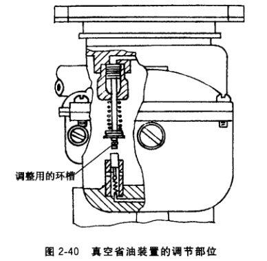
(4) Maintenance of fuel-efficient devices. The Model 231 vaporizer is equipped with a vacuum fuel-saving device and a mechanical fuel-saving device. The vacuum fuel-saving device is controlled by vacuum, and can be adjusted by the 3-way ring tip of the lower end of the piston lever, as shown in Figure 2-40. Adjust a ring groove down,
It is equivalent to relaxing the spring and delaying the action of the vacuum fuel-saving device. Conversely, moving a ring groove upwards is equivalent to strengthening the spring force and acting early. If the piston of the fuel-saving device is seriously worn, the spring is broken or the spring force is insufficient, a new piece should be replaced.
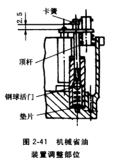
Mechanical fuel vaporizer 231 ,, means to be fully opened before the opening function of about 10 ° in the throttle. When adjusting, the throttle valve is generally opened to the fully open position, so that the fuel-saving device ejector is just in contact with the steel ball. At this time, the acceleration pump connecting piece is flush with the lower circlip groove on the ejector pin, that is, the upper plane distance thereof 5毫米。 Upper circlip 2~2. 5mm. Then lift the connecting piece and install the upper and lower circlips. If the above requirements are not met, increase or decrease the gasket under the valve assembly, as shown in Figure 2-41 , to change the height of the ball valve group .
(5) Accelerate pump inspection and adjustment. When inspecting the accelerating pump , first check the integrity of the piston leather bowl, not loose, up and down Inflexible movement, wear, missing edges, etc., should be replaced if necessary, so as not to accelerate the pump failure. When the piston is installed, the piston push rod can be repeatedly pressed and lifted by the hand to move the piston up and down, and the pump oil is inspected from the acceleration nozzle.
After the acceleration pump is inspected, if the inlet and outlet valves are clogged, they can be cleaned with gasoline and then blown with compressed air.
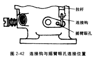
The amount of oil that accelerates the pump sprayer should be adjusted as the season changes. It is adjusted by connecting the hook hole of the accelerating pump pull rod to the acceleration pump rocker arm . The summer connection hook should be hung in the rocker hole close to the throttle shaft, and the winter should be hung in the left eye hole, as shown in Figure 2-42.
The Model 231 carburetor also reliably accelerates the adjustment of the two ring grooves on the upper end of the pump piston rod. If the connecting piece is connected with the lower ring groove, it is equal to the increase of the piston stroke and the pump oil quantity increases.
(6) Adjustment of idle speed. When adjusting the idle speed, the ignition system, gas distribution mechanism must work properly, the cooling water reaches a temperature of 80-90 deg.] C, each liner, duct seal intact. Having prepared the above-described conditions, only idling adjustment. There is an abnormality, and the speed is not adjusted well, and it can't even be adjusted.
1 All the chokes are opened, and the throttle opening adjustment screw is screwed out with a screwdriver , and the gasoline engine reaches the minimum speed and is not extinguished .
2 Use a screwdriver to turn the idle adjustment screw so that the gasoline engine is about to turn off the flame, then slowly unscrew it to make it run stably and reach the highest speed. Then, the throttle opening adjustment screw is screwed out to reach the minimum speed, which is limited to no flameout.
3 The two adjusting screws should be matched with each other and adjusted repeatedly. When the throttle opening is minimum, the gasoline engine runs at the lowest stable speed. Generally, it is suitable to see the blades of the cooling fan rotating during idle operation.
4 After the adjustment, the gasoline engine speed is increased, and the throttle valve is suddenly closed. The gasoline engine is not turned off, and it is suitable to operate stably. If the flame is turned off, turn the throttle adjustment screw slightly to increase the speed slightly.
(7) Inspection of the throttle shaft. Due to long-term use, will affect the lazy, medium and high speed when the throttle shaft and bore wear serious, it must be repaired in time. When the throttle shaft wears and the clearance exceeds 0.10mm, it should be replaced with a new one. For temporary use, the solder can be thickened in the worn place, and then trimmed with a file according to the specific situation. After the assembly, it can be rotated freely and the gap can be suitable. When the throttle is not tightly closed, the throttle of the steel sheet can be placed on the platform, and the periphery of the steel sheet is gently tapped with a small hammer to make it slightly larger, and then trimmed with a file to close the throttle and the mixing chamber wall. If the throttle is made of zinc alloy, the bump can be scraped or scraped off with a trowel or scraper to make the circumference flat and tightly closed.
Escalator Components
- Down Driving Device , 30° Angle
- Yellow Taut Bow Used For Escalator / Escalator Components
- Durable Clamping Panel Used For Schindler Escalator
- Roller Arc Parts For Escalator Components
product
- SWE Upward Driving Device For Escalator , Escalator Components
- Yellow Comb Plate , Escalator Components / Parts
- Finger Protective Switch For Escalator Components / Parts
- Reversing Chain , Durable Escalator Parts
- Durable Clamping Panel Used For Schindler Escalator


Escalator Components
Escalator Components, Support Roller, Down Driving Device, Durable Clamping Panel
Ningbo Xinda Elevator Traction Technology Co., Ltd. , https://www.xinda-elevator.com