Yao Bo Lu Weiqing
(Shanghai Anke Rui Electric Co., Ltd., Shanghai Jiading 201801)
Abstract: This paper introduces the design and application of an economical smart motor protector-ARD2. The protector integrates many protection functions and protects the motor from various faults encountered during actual use. Under the fault conditions, no damage will occur, the reliability of the motor operation will be improved, and the production loss due to the motor failure problem will be reduced.
Keywords: Motor Protector, ARD2, Protection, Economy
0 INTRODUCTION Due to the emergence of production automation and various automatic control and sequential control equipments, the motor is often operated in frequent starting, braking, forward/reverse, intermittent and variable load modes, and the running requirements of the motor are getting higher and higher. The environment is becoming more and more demanding. At the same time, as the motor is connected with the supporting machinery, when the motor fails, it often affects the production system. Therefore, the effective protection of the motor is an important task to ensure the normal operation of the production system.
This article will introduce the economical, simple design method and application of ARD2 motor protector. This type of protector is mainly used to monitor the running state of the motor, and it is aimed at the start-up timeout, under-voltage, over-voltage, under-load, overload, short-circuit, stall/block, phase failure, and unbalance of the motor during the production operation. Faults such as residual current (earth/leakage current) are protected so that the motor will not be damaged due to the above reasons, thus causing production losses. Using ARD2 motor protectors can effectively improve the safety of motor operation and reduce production losses. It is a tradition. Ideal replacement for thermal relays.
1 Technical specifications of the ARD2 intelligent motor protector are shown in Table 1.
Table 1

2 Design methods Currently, the design of the integrated smart motor protector on the market mainly adopts the scheme of AC sampling + high-performance single-chip. The motor protector adopting this design method has many measurement parameters, high measurement accuracy, and can provide more perfect protection functions. However, the cost of adopting this design method is high, and the selling price is also high. In the case where only the motor is required to provide overload, breakage, and other basic common fault protection, there is no cost-effectiveness. Therefore, a smart motor protector that is simple in design and can satisfy basic protection requirements and is mainly used to replace thermal relays will have a large market. The ARD2 protector is an economical smart motor protector with a simple design, a large number of protection functions, and the ability to meet most motor protection requirements.
The ARD2 intelligent motor protector adopts a low-cost design scheme. The overall system consists of a signal processing unit, a central processing unit, a power supply module, a human-machine interaction unit, a human-machine interface, a control module, and a communication interface module. The hardware structure of the device is shown in the figure. 1 shows.

figure 1
2.1 Signal Processing Unit The signal processing unit adopts a rectifying and amplifying filter circuit. As shown in Fig. 2, the circuit can rectify the AC signal obtained by sampling into a DC signal, which is converted by the CPU chip AD.
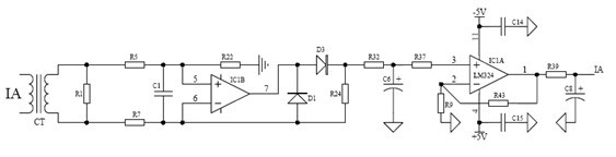
figure 2
IC1 is the operational amplifier LM324 in the picture, adopts the dual power supply, this can guarantee LM324 output voltage reaches 5V to make full use of A/D conversion to improve the display precision. IC1 performs two-stage amplification processing on the signal obtained by sampling, which improves the sampling accuracy of the signal and ensures the linearity of the signal.
2.2 Central Processing Unit The central processing unit uses the first MC9S08AW32 high-performance microcontroller based on the highly energy-efficient S08 core from MOTOROLA. The microcontroller has ample on-chip resources and outstanding anti-interference ability. Contains 32K bytes of user program space, on-chip 2K of RAM, support for BDM on-chip debugging, on-chip integrated watchdog circuitry, and on-chip 8-channel 10-bit AD. The external expansion of the ferroelectric memory is used to store some important parameters, even if the upgrade program will not lose the previous important data.
The CPU processes and calculates the sampled signal, and compares the measured current and voltage values ​​with various preset protection values ​​to determine whether the motor operation state is normal and whether protection is needed. Central processing unit circuit shown in Figure 3.

image 3
2.3 The power module uses the AC380V power module. The power module input voltage is AC220V ~ 450V, input frequency 45Hz ~ 60Hz, the output voltage is stable, the failure rate is small, output ripple <1%, conversion efficiency ≥ 75%. With over-voltage, over-current protection. The module is used on the actual site and has high stability, reliability and anti-jamming capability.
2.4 Man-Machine Interaction Unit The man-machine interaction unit uses LED display and key input. The system uses a single row of four LED digital tubes to display various information. Users can set according to actual needs. Menus and parameters are displayed in the programming state. The digital tube display adopts the dynamic scanning method, and the driving circuit uses a 74HC595 plus triode.
2.5 Control Module The control module is mainly composed of digital inputs and outputs, see Figure 4. The digital input is used to monitor the status of the external switch. It can also be used to start and stop the motor according to customer requirements. The digital output is mainly used to output alarm signals, trip signals and remote start signals.

Figure 4
2.6 Communication Interface Module The communication interface module adopts common RS-485 and Modbus RTU communication protocols, which can realize functions such as telemetry, remote control, and remote signaling, as shown in Figure 5.

Figure 5
2.7 The overall design of the protector adopts the separation structure of the main module and the current transformer module as shown in Figure 6. This structure is ideal for installation in a drawer switchgear. During installation, the protected main part with display is embedded in the movable panel of the switch drawer, which simplifies the wiring in the cabinet, facilitates system adjustment at any time, sets parameters, displays, and monitors, and the digital display panel is also The unity and aesthetics of the cabinet are added, making the equipment operation situation and fault status in the power distribution room clear at a glance, which greatly facilitates system inspection and maintenance. The transformer part adopts the DIN35 guide rail installation method, in order to be able to replace the current transformers of different ranges according to the user's measurement requirements.

Figure 6
2.8 Software Design The main software flow diagram of this product is shown in Figure 7. The main program includes A/D subroutines, protection subroutines, calculation and display subroutines, key processing subroutines, communication subroutines and other subroutines. More, now only the main program flow and protection subroutine flow chart are shown in Figure 8.

Figure 7
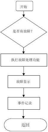
Figure 8
3 Function Introduction ARD2 intelligent motor protector can be divided into AC380V, AC220V according to the rated working voltage; according to the working current range can be divided into 6.3A (1.6A ~ 6.3A), 25A (25A ~ 100A), 100A (25A ~ 100A) ) 250A (63A to 250A) and 800A (250A to 800A) five measurement positions. Realize the start-up timeout, under-voltage, over-voltage, under-load, overload, short-circuit, blocking/blocking, phase failure, unbalance, residual current (ground/earth leakage) and other faults that occur during motor operation. And can add a variety of additional functions based on this, mainly include:
1) Remote start function: The remote starter motor can be realized by the host computer through the start relay of the communication control protector.
2) Alarm function: When the motor running status is faulty, it will alarm before it reaches the preset trip time.
3) Communication function: RS-485 communication function, through the communication interface, the various parameters of motor operation detected by the protector can be transmitted to the background main control equipment in real time, so that the working personnel can understand the working status of the motor in time.
4) Leakage protection: open leakage protection monitoring function, when the leakage of electricity in the operating environment of the motor, cut off the power supply of the motor in time.
5) Switch input: It is used to monitor the switching state of the external switch. It can also start and stop the control according to the customer's requirements.
6) Event record: record the time and reason of the last 8 tripping actions of the protector, which is convenient for maintenance personnel to view and repair.
7) 4 ~ 20mA analog output: provide 4 ~ 20mA DC current signal.
4 Typical Applications Figure 9 shows a typical application diagram of the ARD2 smart motor protector with direct start connection. The user can start the motor by pushing the external start button SB2 or by the upper machine remote control protection starter relay. The control method is: when the start button SB2 is pressed or the remote start relays 7 and 8 are closed, the attraction coil of the contactor KM is in an energized state, the main contact of the contactor KM and the self-locking contact KM are closed, and the motor is started. At this point, the SB2 is released or the relays 7, 8 are opened and the attraction coil of the contactor KM is still in an energized state. The main contact and the self-locking contact KM are still in the closed state and the motor is in the energized state. Once the motor is normally started, the protector monitors the operating status of the motor. When the motor is in a fault state, the trip relay of the ARD2 protector acts, and the normally closed contacts 95 and 96 are disconnected, making the contact coil of the contactor KM attractive. When the power is turned off, the state of the main contacts and self-locking contacts of the contactor KM is changed from unity to division, and the power supply to the motor is cut off to stop the motor.

Figure 9
Fig. 10 is a typical application diagram of an ARD2 intelligent motor protector with a Y-? In FIG. 5, the contact state of the time relay KT is the state when the attracting coil is de-energized, ie, "normal state." When the start button SB2 or the remote start relays 7 and 8 are closed, the coil of the contactor KM1 is energized to close the main contact of the KM1 and the self-locking contact KM1, and at the same time, the time relay KT attracts the coil to be energized. Due to the delay, its The contact does not act immediately, so the coil of the contactor KM3 is energized, the main contact of the KM3 connected to the main circuit is closed, the star connection of the motor is started in a step-down manner, and the interlocking contact of the KM3 is disconnected, so that the contactor KM2 The attraction coil cannot be energized, and the motor runs on the Y-type power supply. When the time delay of the time relay KT is reached, the normally closed contact of the time relay KT is turned off, the contactor KM3 draws the coil off, the main contact KM3 is disconnected, and the delay of the time relay KT is closed. When the open contact is closed, the attraction coil of the contactor KM2 is energized, the main contact KM2 is closed, the motor power supply mode is changed to the “type†connection, and the normal operation state is entered. At the same time, the interlocking contacts of the KM2 are disconnected so that the contactor KM3 attracts the coil without energization. Once the motor is normally started, the protector monitors the running status of the motor. When the motor is in a fault state, the trip relay of the ARD2 protector acts, and the normally closed contacts 95 and 96 are disconnected, making the contact coil of the contactor KM attractive. When the power is turned off, the state of the main contacts and self-locking contacts of the contactor KM is changed from unity to division, and the power supply to the motor is cut off to stop the motor.

Figure 10
5 Selection Note In the actual use, care should be taken to select the protector in strict accordance with the rated current of the motor to prevent artificial amplification and reduction of the protection range; to avoid measurement errors caused by too large or too small ranges, so that the protector cannot Normally protect the motor.
Since the ARD2 protector adopts a structure in which the main body module and the current transformer module are separated from each other, it is necessary to use the factory serial number to match the main body of the protector with the transformer when using it in the field. However, considering that there will be maintenance and replacement of protectors or transformers, as long as the protector body and the transformer are of the same product type, they can be randomly allocated and used without affecting the measurement protection.
The protector is designed to replace the thermal relay, so the protector itself does not provide start and stop control of the motor and various start control methods. The realization of various starting control methods for the motor requires the support of external circuits.
6 Conclusion The ARD2 intelligent motor protector has many functions and can accurately display and trip the various types of faults encountered in the operation of the motor. It can effectively prevent the accidental burning of the motor and save a lot of users' lives. The funds are an ideal alternative to thermal relays. Therefore, the widely used motor intelligent protector not only can improve the accuracy, scientificity, and accident rate of the process control, but also can play a positive role in promoting the automation level of the electrical control system and developing the national economy.
Article from: "machine tool electrical appliances" 2008 the third period.
references
[1] Shanghai Ankerui Electric Co., Ltd., ARD2 Smart Motor Protector Selection Manual, 2007.
[2] China Electric Power Press, Electrical and Electronic Technology, 1999.
Quacent is a Canadian invested plant & specializing in prefab house for residential and commercial construction.
We adopt the latest technology such as Structural Insulated Panels (SIPs), Light Gauge Steel (LGS), Timber Frame (2x4) etc., to make durable, and energy efficient, sustainable, and cost effective houses with highest possible prefabricated rate.
SIPs, the latest approach in the housing industry & our main building
system, can create a strong, durable and energy efficient building envelope in
a very short time. A well-built SIPs homes can reduce annual energy cost by 50
percent or more which greatly cut down on carbon dioxide emissions.
Prefabricated SIPs also save builders a significant amount of onsite labor and generate
0 waste. We have set up the first manufacturing line for SIPs in China &
lead the SIPs industry. Our full automatic Light Gauge Steel
equipment also enables us to provide LGS house.
By our strong R&D, strict QC and full technical support, our prefabricated homes have been set up in many countries such as Canada, Germany, Netherland, Sweden, Russia, Australia, Japan, etc. Quacent prefab houses have gained reputation world-widely.
Our goal is to build the house greener, faster, stronger, more comfortable, and more energy saving.

Prefab Homes,Prefabricated Homes,Assembly House,Fast Assembly House
Dalian Quacent New Building Materials Co.,Ltd. , https://www.quacenthomes.com