Modular design shortens product design cycles, reduces costs, and enhances product competitiveness. For mechanical products such as machine tools, the static and dynamic characteristics of the mechanical structure are important for product use. The dynamic characteristics of a single module and a combination of many modules are the most concerned issues for designers. If you understand this at the design stage and optimize the structure accordingly, it will greatly improve the design quality of the product.
Dynamic analysis and optimization of mechanical structure is a relatively independent CAE part. At present, many powerful CAD system software (such as UniGrå©hics, Catia, Pro/E, SolidWoiks, etc.) are generally different from finite element analysis software. The database format used is different and cannot be directly integrated. To realize the static and dynamic characteristics analysis and variable structure optimization of CAD modules, the data integration from CAD module to CAE is the key to problem solving.
2 Generalized modular design framework based on finite element dynamics analysis The generalized modular design includes many aspects. The modular design centered on the static and dynamic characteristics analysis and optimization of mechanical structures is one of the branches. The framework of the design process is as shown.
The design process analyzes the user's needs, selects or builds a new module from the module library according to the function-structure mapping. The module should contain all the information of the actual physical module (geometric information and non-geometric information). 2) CAE (paper design analysis) Can analyze and test whether the module has structural interference or motion interference, etc. The result can be fed back to the CAD module to modify its structural size, etc. 3) Extract some of the information from the CAD module (including geometry, material properties, joint surface parts, Load-bearing information, etc., establish a virtual modular design finite element model based on finite element dynamic analysis and structure optimization. 4) Finite element model pre-processing includes simplified model, selection of element type and meshing, etc.; 5) finite element static analysis It can analyze the static characteristics such as stress and strain of the structure; 6) finite element dynamic analysis including modal analysis, transient analysis, spectral analysis, multi-load step dynamic analysis, etc., can analyze the dynamic characteristics of the natural frequency and mode shape of the structure. ,and with.
The main process of the central database method for exchanging data between the CAD model and the finite element model is as follows: Since the finite element analysis tool software ANSYS cannot directly extract data from the CAD model database, data can only be transmitted through the data file, which will affect its work. Efficiency, but model optimization based on dynamic and static characteristics analysis is a relatively independent CAE part, and the data transmission frequency requirement is not high with CAD model. This process can ensure that the data used in the ANSYS model before and after the model and the data used in the solution are in the same database of AN-SYS until the optimization is completed.
3.4 Secondary development of module model in ANSYS ANSYS is a professional CAE software. In addition to the knowledge of the depth and breadth of the user, the user needs to master the specific operation method of ANSYS. However, using the parametric design language provided by the software, APDL, to re-develop the software can simplify the operation process and make the optimization design more compact. For the structural optimization design of variables (parameters), ANSYS can be called as a subroutine in VC or FORTRAN.
Using external files to achieve data transfer between the database and the finite element variable model (down to page 34) Other conditional variables Data text files need to be optimized (virtual) modules without optimization (virtual) module limited mode After the element type is compensated by the tool radius, the tool center track related data is transmitted to the DSP motion controller through the man-machine interface, and the DSP motion controller can be started to drive the 2D working platform to accurately shift, and the analog milling cutter will be used. The trajectory of the workpiece to be machined and the tool center trajectory are accurately reproduced. Comparing, it can be judged that the numerical control system is still ideal.
8 Conclusion The computer numerical control system discussed in this paper involves DBP, Java Matlab and other technologies to achieve tool radius compensation, acceleration and deceleration control, linear and arc real-time numerical interpolation. Of course, further research is needed in the following aspects: realizing accurate control of on-site machine tools, dynamically constructing acceleration and deceleration control curves of the system, and realizing remote network diagnosis and control.
The actual output path of the system and the tool center track Note: In this example, the tool compensation direction is left and the tool radius is 3mm. The macro file division of the finite element model should be consistent with the module division, and the modular design process should be followed. In order to reduce the number of macro files for management, a base module and its variant modules have a macro file module; in order to facilitate the normal application of boundary conditions during design, the macro file module is at the lowest level to the module (part) level.
4 Conclusion The smooth transfer of data between CAD model and finite element model can ensure the consistency of design data, and it is the premise of subsequent model dynamic and static performance analysis and model structure optimization. The actual work proves that the method is simple and practical and has been applied to the modular design of hydraulic presses.
(Finish)
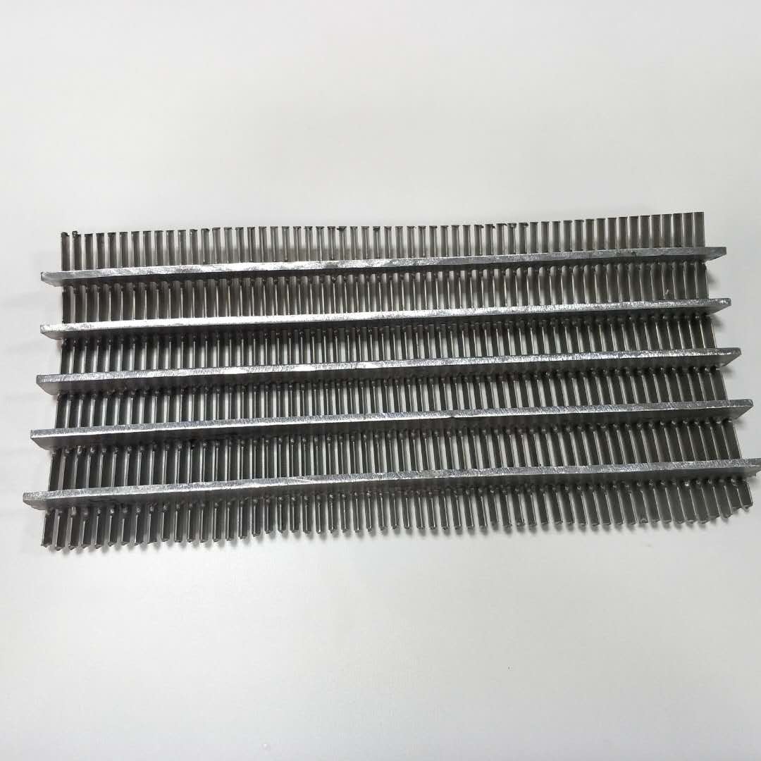
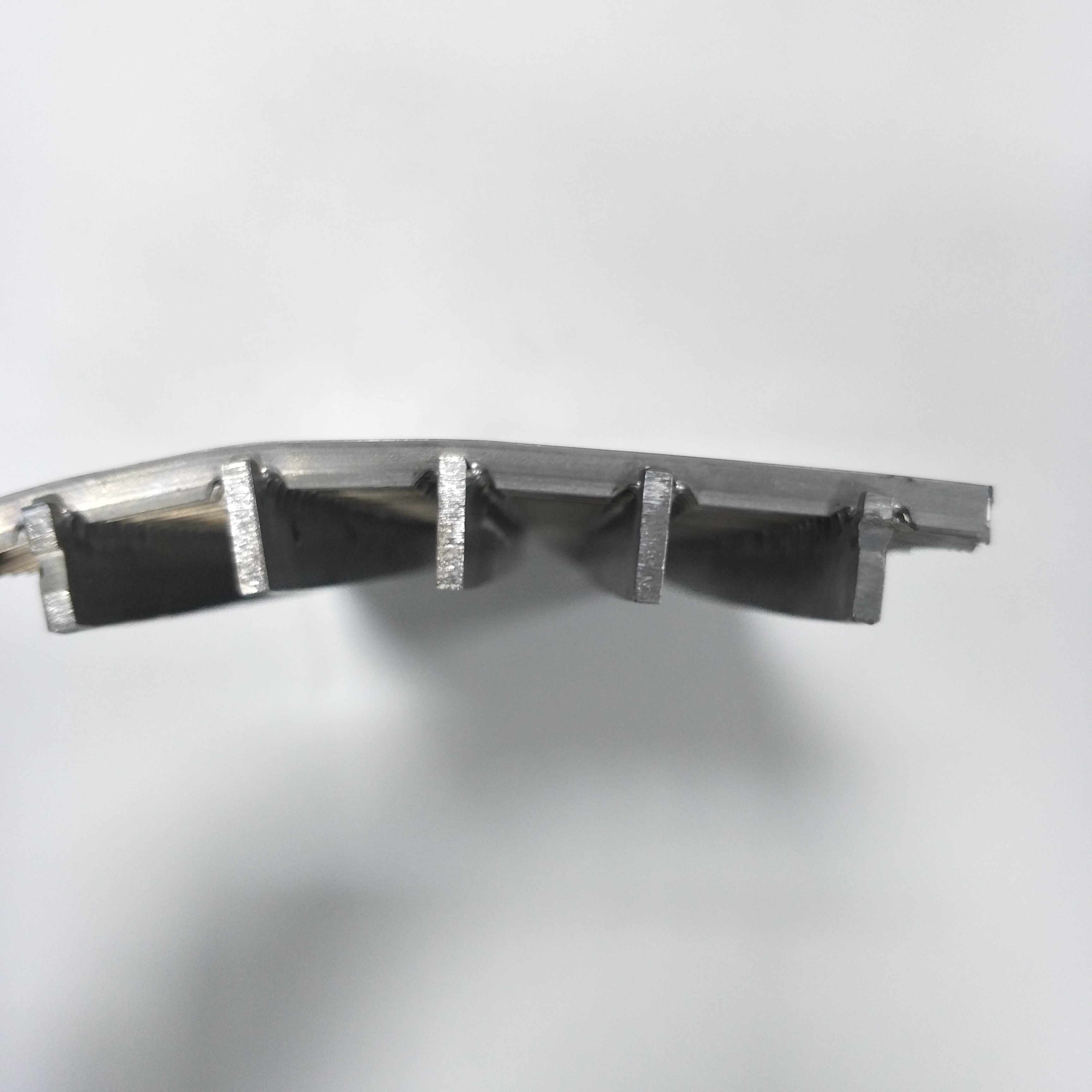
Curved Platelike Johnson Screen is a kind of platelike Johnson screen. It is made up of several support rods and wedge shaped surface wire. The size of slot opening is controllable.

The arc filter can effectively reduce the concentration of suspended matter in water and reduce the treatment load of subsequent processes. It is also used in industrial production for solid-liquid separation and recovery of useful substances.

The material of stainless steel ensures the high mechanical strength, no deformation, long service life and easy to clean.
Curved Platelike Johnson Screen
Stainless Screen,Curved Platelike Johnson Screen,Stainless Steel Curved Platelike Johnson Screen,Ss Curved Platelike Johnson Screen
Xinxiang Shengda Filtration Technique Co., Ltd. , https://www.filtrations.nl