Planning and Design of DCS System Control Scheme for Flue Gas Desulfurization Technical Improvement Project of Huangtai Power Plant
I. Project Overview
This project is a flue gas desulphurization technology improvement project for 2×300MW (2×1025t/h coal-fired boiler) #7 and 8 units in Shandong Huangtai Thermal Power Plant. It is the first 2×300MW unit in China for flue gas desulphurization (Fuel Gas Desulfurization, below Referred to as FGD) domestic demonstration project. The flue gas is desulphurized using the internationally accepted limestone-gypsum wet process, and the flue gas systems, absorption towers, oxidation fans, first-stage cyclone dehydration and other desulfurization devices are used in the #7 and #8 furnaces; the limestone absorbent is used; Preparation, accident pool, secondary dewatering, industrial water, wastewater treatment and other auxiliary systems are common. Separate gypsum frying workshop. The general technical responsibility of the project and the general contractor of the project is Beijing Guodian Longyuan Environmental Protection Engineering Co., Ltd. The desulfurization technology is the introduction of limestone from the German company Stan Miller (now the German company Bargko Energy GmbH, abbreviated as BBP). Gypsum wet desulfurization technology is mature and reliable, and it has an advanced level in the world of desulfurization. 
The control system of the desulfurization system is based on the Distributed Control System (DCS), which automatically controls the desulfurization systems and common auxiliary systems of the #7 and 8 units. DCS of this project has tendered and adopted the I/A system of Shanghai Foxboro Co., Ltd. which was used by old plants of power plants #7 and 8. 
The desulphurization project was designed, installed, and commissioned after one and a half years of intense construction drawings from July 2002. The #8 unit desulfurization and utility auxiliary system successfully passed the 168 trial operation on December 25, 2003. The team's evaluation is "it really deserves a demonstration of learning." 
1.1 Overview of Desulfurization Process System
This project uses a limestone-gypsum wet desulfurization process system. The main process systems include limestone slurry preparation systems, limestone slurry supply systems, absorption tower systems, absorption tower oxidation air systems, slurry discharge systems, gypsum dehydration systems, process water systems, industrial water systems, and flue gas systems. Limestone slurry preparation system includes dust collector, iron remover, vibrating feeder, vertical hammer crusher, bucket elevator, scraper conveyor, weighing belt conveyor, wet ball mill, etc.; limestone slurry supply system includes limestone slurry tank , Limestone slurry pumps, etc.; absorption tower systems include absorption towers, circulating slurry pumps, gypsum slurry discharge pumps, etc.; absorption tower oxidation air systems including oxidation fans; etc.; slurry discharge systems including slurry discharge systems in the Art Building area and accidental slurry discharge in the absorption tower area System; gypsum dehydration system includes a primary dehydration system (including gypsum cyclone station) and secondary dehydration system (vacuum belt dehydrator, vacuum pump, etc.). 
1.2 DCS control range
The scope of DCS control includes the limestone-gypsum wet desulfurization process system with two furnaces and two towers above, ancillary utility systems, and electrical desulfurization transformers, and plant power consumption. The gypsum dry frying workshop has a separate PLC subsystem. 
1.3 Control Methods and Automation Levels
The entire desulfurization system uses a centralized monitoring method. The operator monitors and controls the system through the LCD, keyboard, and track ball marker in the centralized control room. The #7 and #8 furnace desulfurization and auxiliary public systems have a centralized control room and are arranged in the electric control building of desulfurization unit of #8 furnace. However, since the #7 furnace desulfurization process system is relatively far from the centralized control room (approximately 400 to 450 meters), the DCS cabinet of the #7 furnace desulfurization system will adopt the "physical dispersion" scheme, ie the desulfurization distribution in the #7 furnace. A separate DCS electronic equipment room is set up for the arrangement of host control cabinets, I/O cabinets, power supply cabinets, and other required control panel cabinets for #7 desulfurization DCS to complete the on-site desulfurization system for #7 furnaces. Data acquisition, automatic adjustment and interlock protection control. The operating personnel will perform complete monitoring of the desulfurization system of the #7 furnace through the DCS computer control network (redundant fiber cable) at the terminal operator station in the #8 furnace desulfurization centralized control room. 
In this project, two units of desulfurization systems share one set of distributed control system (FGD-DCS) for control, and three operator stations are set up in the desulfurization centralized control room. The operator uses the LCD and keyboard of the DCS operator station as the main monitoring and control center in the desulfurization control room, and is equipped with a small number of backup emergency hard operation buttons (three flue damper doors and booster fan switch hard Buttons, etc., which are arranged on the #7, 8 furnace desulfurization correspondent operator station), can perform start/stop control, normal operation monitoring and adjustment of the desulfurization systems and common systems of the two units, and alarms for abnormal conditions. Emergency handling without the need for on-site personnel to cooperate. 
1.4 control functions
DCS of this project includes the following main functions:
Data Acquisition (DAS)
◠Analog Control (MCS) 
◠Sequence Control (SCS) 
â— Electrical desulfurization transformer, plant power control (ECS)
1.5 DCS control scale
1.5.1 I/O Points
The total number of DCS thermal I/O points for this project is approximately 2363 points, including 777 points for #7 furnace desulfurization system, 725 points for #8 furnace desulfurization system, 861 points for common auxiliary systems, and 254 points for electrical systems. Detailed thermal control I/O point classification statistics are shown in the following table: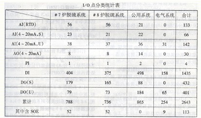
◠The above quantities do not include spare points and hard-wired contact points inside the DCS. 
◠The "S" in the above table represents the power supply within the DCS, and the "U" represents the power supply from outside the customer. 
1.5.2 Control Objects
The number of DCS controlled objects in this project is approximately 391 (excluding electrical desulphurization, plant power consumption), among which 129 desulphurization systems for #7 furnaces, 119 desulphurization systems for #8 furnaces, and 141 public systems. The detailed classification statistics are shown in the following table: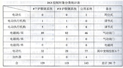 Second, DCS system configuration and characteristics
According to the characteristics of the desulfurization process system, the DCS operator station, process control station (including the control main cabinets and processors CP, I/O cabinets and modules, output relay cabinets, and power distribution cabinets, etc.) are subject to the following physical dispersion. The principles are grouped:
1) #7 boiler FGD desulfurization process control station, control physical dispersion scope includes #7 furnace FGD desulfurization tower, circulating slurry pump, oxidation fan, booster fan, gypsum cyclone dehydration, and GGH. 
2) # 8 boiler FGD desulfurization process control station, control of physical dispersion includes # 8 furnace FGD desulfurization tower, circulating slurry pump, oxidation fan, booster fan, a gypsum cyclone dehydration, and GGH. 
3) FGD public auxiliary part process control station, control physical dispersion scope includes public limestone absorbent preparation, accident slurry system, secondary vacuum belt dehydration, industrial water, wastewater treatment and so on. 
DCS system structure configuration details as shown below:
The I/A system structure consists of three layers. The uppermost layer is the plant information management layer, the next layer is the process operation control layer, and the third layer is the process control and process interface. The entire system consists of an operator station, an engineering station, a process control station, a power distribution cabinet and a communication system. See the DCS main control module and peripheral equipment configuration table for the device configuration details. 
2.1 Man-Machine Interface (MMI)
The desulfurization unit DCS of this project has three operator stations (including one #7 furnace desulfurization system, one #8 furnace desulfurization system, one public system) and two engineer stations (including one #7 desulfurization system). # 8 furnaces and public systems 1). 
Printer configuration: 1 A4 color laser (hanging #8 furnace desulphurization engineer station), 1 A4 color inkjet (hanging #7 furnace desulphurization engineer station), 2 A3 network wide line records (hanging DCS network communication processor COMP10). 
2.2DCS Cabinet
The I/A system uses a total of 17 DCS cabinets in this project, including 3 main cabinets (including #7 furnace desulfurization system, #8 furnace desulfurization system, and 1 utility system each), and 6 relay cabinets (including #7 furnace Two desulfurization systems, two #8 furnace desulfurization systems and two public utility systems), six FBM card cabinets (including #7 furnace desulfurization system, #8 furnace desulfurization system and two utility systems each), and two power distribution cabinets (including one # 1 furnace desulfurization system, # 8 furnace desulfurization system and a public system), cabinets are 2200 × 800 × 800 (mm). 
2.3 Process Control Processor (CP)
Two pairs of redundant CPs (#7 for CP6001 and CP6002, #8 for CP6003 and CP6004, and public systems for CP6005 and C6006) are used for the #7 furnace desulfurization system, #8 furnace desulfurization system, and desulfurization common auxiliary system, respectively. It mainly completes the I/O sampling, processing and process control of the respective process systems. 
2.4 Process I/O Cards (FBM)
The configuration of the module requires the DCS manufacturer to configure according to the process system and DCS function during the bidding. DCS main module configuration details are as follows: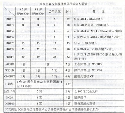
2.5DCS Communication System
The communication system is 1:1 redundant and the communication mode is broadcast. 
The communication network of the I/A system provided by this project is divided into three layers: field bus, node bus, and management information bus. 
2.5.1 Fieldbus 
The fieldbus is used for the communication between the CP40B control processor and the Fieldbus Module (FBM), the I/O card. Fieldbus communication interface is EIARS485, communication speed is 268.5KBPS, communication protocol IEEE1118, shielded twisted pair or optical cable. 
2.5.2 Node Bus
The node bus is used in the process management control layer to provide high-speed (10MB/S), redundant point-to-point for each station (application processing station, control processor, operation station processor, etc.) in the I/A system. communication. The bus is a straight-chain structure, the communication protocol is IEEE802.3, shielded twisted pair or fiber optic cable. 
The DCS system of this project consists of two contacts (each node can be connected to 64 stations): #7 furnace desulfurization system contacts, #8 furnace and public desulphurization system contacts, and the two connections are connected by LAN LAN (with redundancy Optical cable). 
2.5.3 Management Information Bus
Through the standard Ethernet TCP/IP communication interface of the engineering station, the plant-wide management information MIS network and the desulfurization DCS control network can realize two-way communication (but generally in safety considerations, all set to one-way data transmission from the DCS to the MIS). Various types of production of real-time information and data can be transmitted over the network to managers with different needs. 
2.5.4 Communication Interface
(1) Internal Communication Interface - Device Integration Processor (COMMP10) and Printer
The device integrated processor has four RS232-C compatible serial interfaces, and its asynchronous communication rate is 9.6Kbps, which can connect peripherals. For example, 80/136 columns of Chinese / English dot matrix printers; color inkjet printers; VT-100 video terminals; modems and PCs and other communications equipment. Each COMMP10 integrated processor can connect eight devices through the asynchronous communication interface. The communication protocol is MODBUS RTU. Other popular communication protocols are available. 
(2) External Communication Interface - Communication Processor (MG30)
The communication processor (MG30) is an interface that communicates with other intelligent control devices (such as PLC). The MG30 processor hangs on the node bus and connects to the computer and the information network. Desulfurization DCS through MG30 and other control systems such as auxiliary gypsum frying workshop PLC subsystem, smoke emission detection system, # 7 unit DCS, # 8 unit DCS, or the whole plant SIS monitoring communication connection. 
2.5.5 Hardwired Signal Interfaces
In addition to configuring the above communication interfaces, the desulfurization DCS also exchanges data for some important signals with hardwired DCS and electric dust control systems of #7 and 8 units, including the boiler status (MFT, flame, purge, etc.), and the input status of the oil burners. , coal burner input status, electric precipitation electric field investment status. The specific signal types and quantities are as follows:
â—Boiler control system sent to desulfurization DCS signal: 
1. Boiler load command signal 4 ~ 20mA1 point
2 boiler total air volume signal 4 ~ 20mA1 point 
3. Boiler main steam flow signal 4 ~ 20mA1 point 
4. Boiler MFTNO (passive dry contact) 1 point
5. Boiler furnace purge NO (passive dry contact) 1 point
6. Boiler soot blowing NO (passive dry contact) 1 point
7. Boiler oil gun input NO (passive dry contact) 3 points in total (1 point/oil layer)
8. 5 points (1 point/oil layer) of NO (passive dry contact) put into each layer of boiler coal burner
9. Boiler electrostatic precipitator operation NO (passive dry contact) 4 points (1 point/electric field)
◠desulfurization DCS sent to the boiler control system signal: 
1. Boiler desulfurization running (or stopping) NO (passive dry contact) 1 point
2. Boiler desulfurization booster fan running (or stopping) NO (passive dry contact) 1 point
3. Boiler desulfurization bypass damper status signal NO (passive dry contact) 1 point
4. Boiler desulfurization original smoke flapper status signal NO (passive dry contact) 1 point
5. Boiler desulfurization net smoke flapper status signal NO (passive dry contact) 1 point
2.6 DCS Power System
DCS power supply adopts dual-loop power supply, one of which is uninterruptible power supply (UPS), and the other is low-voltage power supply for factory use. The DCS power supply capacity of the #7 furnace desulfurization system is 8 KVA, and the DCS power supply capacity of the #8 furnace desulfurization system and public system is 15 KVA. 
The entire DCS is equipped with two power cabinets, which provide the AC power and 24VDC power required by the #7 furnace desulfurization system, the #8 furnace desulfurization system, and the common system DCS equipment. 
Two AC power sources entering the power cabinet work all the way, all the way back to the DCS internal electronic devices, network systems, operator stations, engineer stations, main cabinets, FBM card cabinets, relay cabinets (including pneumatic valves that require DCS operation to supply power , Solenoid valve) and emergency button on the console, indicating lamp power. 
All the cabinets of the system adopt redundant power supply mode to receive two-way AC power input. The battery back-up power for fieldbus components is provided by the power converter within the associated control processor. DCS operator stations and engineering stations also use redundant power supply methods. One is to supply DCS power supply cabinets and the other is to be powered by a 220VAC power supply cabinet. The two-way power supplies are switched through the automatic AC transfer switch in the control room console. 
This project uses pneumatic doors, which are numerous (approx. 230 or so) and disperse. Therefore, for all the pneumatic door switch control, DCS is required to use the two AC 220V power supplies provided by the user and use terminal blocks with fuse protection switches in the output relay terminal cabinet. Pneumatic door, DCS can output active DO contact signal (AC220V, 0.5A) with direct drive pneumatic door from the relay cabinet. No centralized solenoid valve box is set for the pneumatic valve at the scene. This saves money. The investment cost greatly facilitates construction, commissioning, operation and maintenance. 
2.7 DCS Grounding System
According to the requirements of Shanghai Fox Polo Co., Ltd., the DCS of this project does not require a separate grounding grid. The DCS grounding cable is connected to the electrical grounding network at a single point. The total grounding resistance is less than 1Ω, and all DCS cabinet bases are required to be rubberized during construction and installation. Insulation floating on the ground. 
I/A system grounding is divided into signal shielding ground, system ground and safety ground of electric equipment. In this project, Shanghai Fox Polo Co., Ltd. is set in all main cabinets, FBM card cabinets, relay cabinets and power cabinets of DCS. Signal shielding ground, systematic grounding and safety grounding copper strips, all grounding in the cabinet are all connected to the grounding copper strips of the above cabinets by DCS manufacturers, and the construction unit will connect the grounding copper strips of each of the above cabinets to the DCS power supply. After the total grounding busbar in the cabinet, it is connected from a point to an electrical grounding grid of 0 meters. There is no other grounding point for large electrical equipment within 15 meters of the grounding point. 
Third, the main function of DCS
Due to space limitations, the following is only a brief description of the main functions and features of this project's DCS (figure omitted) for reference when reading. 
DCS main functions include the following parts:
Data Acquisition (DAS)
· Analog Control (MCS) 
·Sequential Control (SCS)
Electrical control system (ECS); mainly refers to the electrical desulfurization transformers, plant power and other systems into DCS monitoring. 
3.1 Data Acquisition System (DAS)
The Data Acquisition System (DAS) is the main monitoring tool for the whole set of desulfurization system in the start, stop, normal operation and accident conditions. Its main functions are as follows:
â— Scanning and processing of process variables
â— Alarm processing
â—Screen display 
â— Tab printing
â— Historical data storage and retrieval
â— Performance calculation: Calculation of desulfurization efficiency, calculation of limestone utilization, calculation of flue gas heat exchanger efficiency, etc.
3.2 Analog Control System (MCS)
Analog control system or closed-loop control system is one of the most important control systems of the unit. 
The main closed-loop control loop (MCS) of the FGD system of this project includes the following:
â—Pressurized fan inlet flue gas pressure regulator
The booster fan needs to overcome the pressure drop from the initial FGD baffle inlet to the end of the net flue gas baffle exit. This loop controls the static pressure at the inlet of the FGD system at -5 mbar. This value is used because the natural draft of the chimney guarantees the static pressure of the outlet when the FGD unit is fully loaded. Pressure control is achieved by adjusting the opening of the inlet guide vanes of the booster fan. In order to optimize the characteristics of the booster fan control loop, the boiler load signal and total air supply signal are introduced as feedforward signals to adapt to the boiler load variation control. 
â— Absorber tower level adjustment
By supplying sufficient process water to the FGD system, the water evaporated from the cooling and saturation process of the hot flue gas entering the absorption tower is replenished. When FGD is in operation, process make-up water is supplied from the rinse water of the droplet separator (demister) and can also be supplied from the limestone preparation system when needed. Absorber tower level control is adjusted by the demister flush water volume added to the actual flue gas. The flushing water volume is controlled by changing the interruption time of the flushing program. The interruption time of the flushing program is a function of the flue gas load. At the maximum amount of smoke, it corresponds to the minimum interruption time. The length of waiting time is controlled. The required lag time of the defogger flushing system is calculated from the measured smoke flow and a function, which is multiplied by a factor determined by the ratio between the normal filling level and the measured actual level. The calculated waiting time, that is, the expected time is compared with the actual waiting time. If the actual waiting time reaches the set value (expected waiting time), a flushing water valve on a layer of the activated demister will be activated and opened (the corresponding defogger rinsing sequence control sub-function group control starts), and the integrator The waiting time will be set to 0. After flushing for one minute, the demister starts a new waiting time for the next rinse water valve on this layer. If the flushing water valve in this layer has been completely flushed, the defogger flush sequence control sub-function group activates the flushing valve flushing procedure next to the defogger. 
◠Limestone slurry flow adjustment 
Accurately controlling the dosing of limestone, ie, a reasonable flow of limestone slurry, will maintain the pH of the liquid environment within the absorption tower within a reasonably optimal range to ensure that all SO2 absorbed by the absorber reacts as gypsum. The control loop adopts a cascade PID control. The primary regulator controls the PH value. The secondary secondary regulator controls the supply of limestone slurry. The output after the primary regulator is introduced into the flue gas flow, and the SO2 concentration in the original flue gas. And some stoichiometric factors are calculated and corrected as the set value input of the secondary secondary regulator limestone slurry flow, and then sent to the secondary secondary regulator for deviation along with the measured limestone slurry supply volume (calculated after flow and density calculation). The PID regulates its output to control the limestone slurry supply regulator valve to quickly respond to FGD load changes, minimizing pH changes. 
â— gypsum slurry discharge adjustment
The amount of gypsum discharged from the absorption tower is directly related to the number of vortexes actually operated by the gypsum primary dewatering cyclone, and the amount of gypsum vortex flow is proportional to the amount of limestone dosing or gypsum generated in the absorption tower. The actual number of swirler operations in the solution configuration is controlled by the density value of the gypsum slurry. Gypsum discharge pump slurry, first measured by online density meter. When the density value is lower than a certain preset value, the number of swirler operations is reduced. Since the pressure in the slurry header of the cyclone station increases, the pressure transmitter on the inlet header of the gypsum cyclone is used. The closed loop control of the signal and gypsum cyclone inlet return pneumatic control valve increases the opening of the return control valve, so that the pressure of the supply header is maintained constant. When the slurry density value is lower than the minimum value (ie, the amount of gypsum production is insufficient), all the cyclones are closed, the reflux control valve is fully opened, and all the slurry containing less gypsum is returned to the absorption tower to continue reacting to form gypsum. Conversely, when the measured density value is greater than the set value, the number of swirlers is increased and the opening of the backflow regulator valve is decreased. When the maximum value is exceeded, all swirlers are turned on and the valve is closed. The pressure of the gypsum supply header during operation always depends on the gypsum slurry return pipe regulating valve to maintain a constant, in order to ensure the normal operation of the running vortex. 
â— Limestone slurry concentration adjustment
Limestone is ground by weighing the belt feeder, and the filtered water is continuously and directly into the wet ball mill according to a set constant amount. At the outlet of the coal mill, the density of the limestone slurry is diluted by controlling the water inflow of the filtered water to the primary recycle tank through limestone slurry density measurement. 
◠vacuum belt filter cake thickness adjustment 
The thickness of the cake was measured using the cake thickness gauge OHTM11CL001 to prevent cake thickness shifts due to changes in supply flow or other causes. In the closed-loop control, the set filter cake thickness value is compared with the actual measured cake thickness value. If the thickness is too large, the speed of the belt motor is adjusted by the frequency converter so that the filter cloth runs at a faster speed if the thickness is too high. Small makes the filter cloth run at a slower speed. 
◠Grinding level of recirculation tank level adjustment 
The volume of the first-stage circulation box is very small, so the range of the liquid level closed-loop control is also very small, and the precision requirement is also high. Usually, the level of the first-stage circulation tank is controlled by controlling the first-stage cyclone overflow return control valve. When the level of the first-stage circulation tank is low, the recirculation control valve will be opened.
◠Level adjustment of the grinding secondary recirculation tank (similar to the adjustment of the level of the recirculation tank at the primary level) 
â—Wind baffle seal air temperature adjustment 
In order to prevent the corrosion of the smoke damper door, the seal wind temperature of the smoke damper must be increased to a certain temperature (about 100 to 110° C.), and the seal air temperature is controlled by controlling the opening of the steam heater inlet steam flow control valve. 
3.2 Sequence Control System (SCS)
Sequential control, ie open-loop logic control, is one of the main control systems of the unit. Its task is to issue an operation instruction in accordance with the start and stop operation requirements and operation status of each device, and to start and stop the main equipment group or subgroup of the unit in sequence. The operator can start, stop or open and close the auxiliary machine through the operator station. 
According to the characteristics of this project, the control level of the desulfurization system sequential control system is considered in terms of functional group level, sub-function group level and driver level three-level control mode. The operating personnel can pass through the operator station to the relevant group of equipment in the functional group and sub-function group. In order to start and stop, it is also possible to start, stop, or open and close a single device in the SCS so that the operator can select a lower level of control in the event of a partial system failure without losing control of the entire process. Simultaneous entry into the SCS also considers interlocking and protection of systems and individual devices. 
The SCS logic design of this project mainly includes the following functional groups and sub-function groups:
A) Flue Gas System Function Group
The fume system function group also includes the following sub-function groups:
â— booster fan sequential control sub-function group
â— Flue damper and its sealed fan (including sealing wind steam heating) sequential control sub-function group
â— GGH sequence control sub-function group
â—GGH steam soot control sub-function group 
◠GGH high pressure water soot-blowing control sub-function group, and so on. 
B) Absorption tower system function group
The absorption tower system function group also includes the following sub-function groups:
â—Circulating slurry pump sequence control sub-function group
◠limestone slurry control sub-function group 
â—Gypsum slurry discharge sequence control sub-function group
Gypsum slurry overflow control sub-function group
◠Demister rinsing sequence control sub-function group 
â— oxidation fan sequential control sub-function group
◠PH meter rinse sequence control sub-function group, and so on. 
C) Limestone preparation system functional group
The following sub-function groups are also included in the limestone preparation system function group:
◠Bag filter sequence control sub-function group (plant for equipment completion) 
◠Iron remover sequence control sub-function group (plant for equipment completion), etc. 
D) Function of the lime slurry grinding system
The following functions are also included under the function group of the lime slurry grinding system:
â—Sequential control sub-function group of weighing belt feeder (plant for equipment completion)
â— Wet ball mill sequence control sub-function group
â— Wet ball mill water supply (including filtered water pit pump) sequential control sub-function group
â— Grind one cycle pump sequential control sub-function group
◠Grind secondary pump sequential control sub-function groups, etc. 
E) Pump discharge system
The slurry discharge system includes the following sub-function groups:
â— Accident tank sequence control sub-function group
◠Each pit pump sequence control sub-function group, and so on. 
F) Other systems also include the following functional groups:
â—Gypsum secondary dewatering system (vacuum dewatering belt) sequential control function group
â—Gypsum dehydration overflow return system sequence control function group
â—Process water system sequential control function group
◠Industrial water system sequential control function group, etc. 
G) Interlock, protection, and alarm logic
The interlock protection of the FGD system mainly includes the following:
◠FGD device interlock protection: Including interlocking protection signal from FGD itself, such as FGD inlet temperature abnormality, inlet pressure abnormality, outlet pressure abnormality, booster fan failure, heat exchanger failure, insufficient circulating pump investment The second is the interlock signal from the host group boiler, such as the boiler MFT, purge, the excessive input of the oil burner, the insufficient input of the coal burner, and the insufficient input of the electrostatic precipitator electric field. 
â—Interlocking protection of important auxiliary equipments (such as wet grinding, vacuum belt, booster fan, GGH, etc.)
◠Others such as start-stop interlocking of standby equipment, tank level interlocking, interlocking of pipeline equipment flushing, etc. 
IV. Optimized Application of "Physical Dispersion" in DCS Solution and Placement of the Project
The desulfurization control system of this project uses a computer distributed control system DCS. A total of one set of DCS is set up, centralized monitoring is adopted, and a centralized control room is set up for the #7 and #8 furnace FGD and auxiliary public system, and is arranged in the electric control floor of the #8 furnace FGD device side. In the original design and review, all DCS control cabinets were placed in the centralized electronic equipment room of the #8 furnace electric control building. During the design of the construction drawings, I noticed that the actual on-site condition is that the #7 furnace desulfurization process system is quite far from the #8 furnace centralized control room (about 380-450 meters), which is technically and economically unreasonable, so I According to the actual situation, the DCS cabinet of the #7 furnace desulfurization system was put forward in a timely manner to adopt the "system decentralized" and "physical decentralization" optimization and modification program, so as to achieve the purpose of technically ensuring the accurate and reliable signal transmission of the system and economically saving investment. 
Specific plans are as follows, and see the DCS hardware configuration diagram: First: The desulfurization DCS control cabinet, FBM card cabinets, relay cabinets, and power cabinets are divided into #7 desulphurization, #8 desulfurization and public auxiliary systems. Independent three groups, DCS system according to this "system dispersed" configuration, to ensure that the three process systems in the operation and maintenance of the relatively independent, without affecting each other, improve the safety and reliability of the DCS. The second will be # 7 furnace DCS from the layout of the "physical dispersion" to the local, in accordance with the current DCS "physical dispersion" approach basically has three options: fieldbus, remote I / 0, and control of the main cabinet scattered. The application of the first type of field bus is currently not yet mature and universal, so it is basically not suitable. The second remote I/O solution is mature and has quite successful application performance. However, if the long-distance communication between #7 furnace desulphurization and #8 centralized equipment fails, the redundant communication channel is used. ), because the control host CP is still in # 8 centralized equipment, the # 7 furnace desulfurization site is completely out of control of the dangerous situation (that is, invisible and can not control any information and equipment), while the third control of the main cabinet scattered solution In the case of all communication failures, because the control host CP, etc. have been dispersed to the local site, its automatic adjustment, interlock protection can continue to operate in the local waiting for the accident to deal with, higher safety and reliability. Therefore, after careful comparison, a third type of control cabinet was used to disperse the program, namely, a separate #7 furnace desulfurization DCS electronic equipment room was installed in the #7 furnace desulfurization gas distribution room, and the original was placed in #8 furnace electronic control. Building centralized desulphurization DCS control cabinets, I/O cabinets, power cabinets, and other required control panel cabinets in the electronic equipment room of the building are all moved to the #7 furnace desulfurization site on the spot to complete the #7 on-site. Furnace desulfurization system data acquisition, automatic adjustment, and interlock protection and other controls. In order to facilitate the on-site commissioning and maintenance and repair of #7 furnace FGD, one auxiliary engineer station is set in the DCS electronic equipment room of #7 furnace. In general, the operating personnel will perform complete and comprehensive monitoring of the desulfurization system of the #7 furnace through the DCS computer control network at the terminal operator station in the #8 furnace desulfurization centralized control room. 
When the DCS cabinet of the #7 furnace desulphurization system is "physically dispersed" to the optimal solution for the electrical equipment of the circulating pump room of the #7 furnace, it is planned to be placed between the centralized electronic equipment of the electric control building of the #8 furnace. In contrast, the optimization results are as follows:
(1) Technically ensure that the system transmits signals more securely and reliably: Because long distances (380 to 450 meters) transmit signals through cables, there will inevitably be serious signal degradation and distortion problems, especially for thermal control thermocouples, thermal resistance, etc. Millivolt-level weak signal. In addition, the transmission of weak electric signals over long distances in a power plant that is subject to severe electromagnetic radiation interference also faces a significant problem of signal anti-interference. With a physically dispersed solution, the transmission of digital optical signals over a network cable is completely immune to electromagnetic radiation, effectively guaranteeing accurate and reliable signal transmission.
(2) Saving a lot of cables: When using physical dispersion, the desulfurization system of # 7 furnace is estimated by 250 cables, each cable length is 380 meters, the cable savings is about 95Km, and the investment can be saved by about 170 to 1.8 million yuan. . 
(3) Saving cable trays: When using physical dispersion, the cable trays of the #7 furnace desulfurization system to the #8 furnace electric control building are conservatively estimated to save three rows of 600 wide bridges, and the cable tray usage is saved at about 40 tons per ton of bridges. The calculation of 0.75 million yuan will save about 300,000 yuan in investment. Others can also save the cost of fireproof partitions, cover plate blocking, coating and other cable fireproof materials. 
(4) Significant savings in construction costs: The cable length will be reduced. In particular, a large amount of cable construction and installation work will be significantly reduced (about one-third of the total project cable laying capacity) into the centralized electronics room of the #8 furnace. Other cable bridges, as well as the amount of fire protection measures for cables, have also been reduced. 
(5) Facilitate and speed up the progress of installation and commissioning: The number of cables and bridges installed in a substantial reduction, can accelerate the progress of the project and shorten the construction period. Moreover, the DCS cabinets of the #7 furnace are distributed nearby, which eliminates the difficulties of long-distance on-site debugging, and greatly facilitates debugging and subsequent operation, maintenance, and overhaul work. 
V. Concluding remarks At present, the flue gas desulfurization construction in China's power industry is still in its infancy. With the country’s increasing emphasis on environmental protection, it will continue to be put into construction. This paper briefly introduces the first 2×300MW flue gas desulphurization technology in China. The planning, design and system configuration of the newly-built flue gas desulfurization system for all new thermal power units or the DCS system control plan for technical upgrading projects are expected to have a certain reference role for future DCS applications in similar flue gas desulfurization projects. If there is any deficiency, welcome criticism. 
This project is a flue gas desulphurization technology improvement project for 2×300MW (2×1025t/h coal-fired boiler) #7 and 8 units in Shandong Huangtai Thermal Power Plant. It is the first 2×300MW unit in China for flue gas desulphurization (Fuel Gas Desulfurization, below Referred to as FGD) domestic demonstration project. The flue gas is desulphurized using the internationally accepted limestone-gypsum wet process, and the flue gas systems, absorption towers, oxidation fans, first-stage cyclone dehydration and other desulfurization devices are used in the #7 and #8 furnaces; the limestone absorbent is used; Preparation, accident pool, secondary dewatering, industrial water, wastewater treatment and other auxiliary systems are common. Separate gypsum frying workshop. The general technical responsibility of the project and the general contractor of the project is Beijing Guodian Longyuan Environmental Protection Engineering Co., Ltd. The desulfurization technology is the introduction of limestone from the German company Stan Miller (now the German company Bargko Energy GmbH, abbreviated as BBP). Gypsum wet desulfurization technology is mature and reliable, and it has an advanced level in the world of desulfurization. 
The control system of the desulfurization system is based on the Distributed Control System (DCS), which automatically controls the desulfurization systems and common auxiliary systems of the #7 and 8 units. DCS of this project has tendered and adopted the I/A system of Shanghai Foxboro Co., Ltd. which was used by old plants of power plants #7 and 8. 
The desulphurization project was designed, installed, and commissioned after one and a half years of intense construction drawings from July 2002. The #8 unit desulfurization and utility auxiliary system successfully passed the 168 trial operation on December 25, 2003. The team's evaluation is "it really deserves a demonstration of learning." 
1.1 Overview of Desulfurization Process System
This project uses a limestone-gypsum wet desulfurization process system. The main process systems include limestone slurry preparation systems, limestone slurry supply systems, absorption tower systems, absorption tower oxidation air systems, slurry discharge systems, gypsum dehydration systems, process water systems, industrial water systems, and flue gas systems. Limestone slurry preparation system includes dust collector, iron remover, vibrating feeder, vertical hammer crusher, bucket elevator, scraper conveyor, weighing belt conveyor, wet ball mill, etc.; limestone slurry supply system includes limestone slurry tank , Limestone slurry pumps, etc.; absorption tower systems include absorption towers, circulating slurry pumps, gypsum slurry discharge pumps, etc.; absorption tower oxidation air systems including oxidation fans; etc.; slurry discharge systems including slurry discharge systems in the Art Building area and accidental slurry discharge in the absorption tower area System; gypsum dehydration system includes a primary dehydration system (including gypsum cyclone station) and secondary dehydration system (vacuum belt dehydrator, vacuum pump, etc.). 
1.2 DCS control range
The scope of DCS control includes the limestone-gypsum wet desulfurization process system with two furnaces and two towers above, ancillary utility systems, and electrical desulfurization transformers, and plant power consumption. The gypsum dry frying workshop has a separate PLC subsystem. 
1.3 Control Methods and Automation Levels
The entire desulfurization system uses a centralized monitoring method. The operator monitors and controls the system through the LCD, keyboard, and track ball marker in the centralized control room. The #7 and #8 furnace desulfurization and auxiliary public systems have a centralized control room and are arranged in the electric control building of desulfurization unit of #8 furnace. However, since the #7 furnace desulfurization process system is relatively far from the centralized control room (approximately 400 to 450 meters), the DCS cabinet of the #7 furnace desulfurization system will adopt the "physical dispersion" scheme, ie the desulfurization distribution in the #7 furnace. A separate DCS electronic equipment room is set up for the arrangement of host control cabinets, I/O cabinets, power supply cabinets, and other required control panel cabinets for #7 desulfurization DCS to complete the on-site desulfurization system for #7 furnaces. Data acquisition, automatic adjustment and interlock protection control. The operating personnel will perform complete monitoring of the desulfurization system of the #7 furnace through the DCS computer control network (redundant fiber cable) at the terminal operator station in the #8 furnace desulfurization centralized control room. 
In this project, two units of desulfurization systems share one set of distributed control system (FGD-DCS) for control, and three operator stations are set up in the desulfurization centralized control room. The operator uses the LCD and keyboard of the DCS operator station as the main monitoring and control center in the desulfurization control room, and is equipped with a small number of backup emergency hard operation buttons (three flue damper doors and booster fan switch hard Buttons, etc., which are arranged on the #7, 8 furnace desulfurization correspondent operator station), can perform start/stop control, normal operation monitoring and adjustment of the desulfurization systems and common systems of the two units, and alarms for abnormal conditions. Emergency handling without the need for on-site personnel to cooperate. 
1.4 control functions
DCS of this project includes the following main functions:
Data Acquisition (DAS)
◠Analog Control (MCS) 
◠Sequence Control (SCS) 
â— Electrical desulfurization transformer, plant power control (ECS)
1.5 DCS control scale
1.5.1 I/O Points
The total number of DCS thermal I/O points for this project is approximately 2363 points, including 777 points for #7 furnace desulfurization system, 725 points for #8 furnace desulfurization system, 861 points for common auxiliary systems, and 254 points for electrical systems. Detailed thermal control I/O point classification statistics are shown in the following table:
◠The above quantities do not include spare points and hard-wired contact points inside the DCS. 
◠The "S" in the above table represents the power supply within the DCS, and the "U" represents the power supply from outside the customer. 
1.5.2 Control Objects
The number of DCS controlled objects in this project is approximately 391 (excluding electrical desulphurization, plant power consumption), among which 129 desulphurization systems for #7 furnaces, 119 desulphurization systems for #8 furnaces, and 141 public systems. The detailed classification statistics are shown in the following table:
According to the characteristics of the desulfurization process system, the DCS operator station, process control station (including the control main cabinets and processors CP, I/O cabinets and modules, output relay cabinets, and power distribution cabinets, etc.) are subject to the following physical dispersion. The principles are grouped:
1) #7 boiler FGD desulfurization process control station, control physical dispersion scope includes #7 furnace FGD desulfurization tower, circulating slurry pump, oxidation fan, booster fan, gypsum cyclone dehydration, and GGH. 
2) # 8 boiler FGD desulfurization process control station, control of physical dispersion includes # 8 furnace FGD desulfurization tower, circulating slurry pump, oxidation fan, booster fan, a gypsum cyclone dehydration, and GGH. 
3) FGD public auxiliary part process control station, control physical dispersion scope includes public limestone absorbent preparation, accident slurry system, secondary vacuum belt dehydration, industrial water, wastewater treatment and so on. 
DCS system structure configuration details as shown below:
The I/A system structure consists of three layers. The uppermost layer is the plant information management layer, the next layer is the process operation control layer, and the third layer is the process control and process interface. The entire system consists of an operator station, an engineering station, a process control station, a power distribution cabinet and a communication system. See the DCS main control module and peripheral equipment configuration table for the device configuration details. 
2.1 Man-Machine Interface (MMI)
The desulfurization unit DCS of this project has three operator stations (including one #7 furnace desulfurization system, one #8 furnace desulfurization system, one public system) and two engineer stations (including one #7 desulfurization system). # 8 furnaces and public systems 1). 
Printer configuration: 1 A4 color laser (hanging #8 furnace desulphurization engineer station), 1 A4 color inkjet (hanging #7 furnace desulphurization engineer station), 2 A3 network wide line records (hanging DCS network communication processor COMP10). 
2.2DCS Cabinet
The I/A system uses a total of 17 DCS cabinets in this project, including 3 main cabinets (including #7 furnace desulfurization system, #8 furnace desulfurization system, and 1 utility system each), and 6 relay cabinets (including #7 furnace Two desulfurization systems, two #8 furnace desulfurization systems and two public utility systems), six FBM card cabinets (including #7 furnace desulfurization system, #8 furnace desulfurization system and two utility systems each), and two power distribution cabinets (including one # 1 furnace desulfurization system, # 8 furnace desulfurization system and a public system), cabinets are 2200 × 800 × 800 (mm). 
2.3 Process Control Processor (CP)
Two pairs of redundant CPs (#7 for CP6001 and CP6002, #8 for CP6003 and CP6004, and public systems for CP6005 and C6006) are used for the #7 furnace desulfurization system, #8 furnace desulfurization system, and desulfurization common auxiliary system, respectively. It mainly completes the I/O sampling, processing and process control of the respective process systems. 
2.4 Process I/O Cards (FBM)
The configuration of the module requires the DCS manufacturer to configure according to the process system and DCS function during the bidding. DCS main module configuration details are as follows:
2.5DCS Communication System
The communication system is 1:1 redundant and the communication mode is broadcast. 
The communication network of the I/A system provided by this project is divided into three layers: field bus, node bus, and management information bus. 
2.5.1 Fieldbus 
The fieldbus is used for the communication between the CP40B control processor and the Fieldbus Module (FBM), the I/O card. Fieldbus communication interface is EIARS485, communication speed is 268.5KBPS, communication protocol IEEE1118, shielded twisted pair or optical cable. 
2.5.2 Node Bus
The node bus is used in the process management control layer to provide high-speed (10MB/S), redundant point-to-point for each station (application processing station, control processor, operation station processor, etc.) in the I/A system. communication. The bus is a straight-chain structure, the communication protocol is IEEE802.3, shielded twisted pair or fiber optic cable. 
The DCS system of this project consists of two contacts (each node can be connected to 64 stations): #7 furnace desulfurization system contacts, #8 furnace and public desulphurization system contacts, and the two connections are connected by LAN LAN (with redundancy Optical cable). 
2.5.3 Management Information Bus
Through the standard Ethernet TCP/IP communication interface of the engineering station, the plant-wide management information MIS network and the desulfurization DCS control network can realize two-way communication (but generally in safety considerations, all set to one-way data transmission from the DCS to the MIS). Various types of production of real-time information and data can be transmitted over the network to managers with different needs. 
2.5.4 Communication Interface
(1) Internal Communication Interface - Device Integration Processor (COMMP10) and Printer
The device integrated processor has four RS232-C compatible serial interfaces, and its asynchronous communication rate is 9.6Kbps, which can connect peripherals. For example, 80/136 columns of Chinese / English dot matrix printers; color inkjet printers; VT-100 video terminals; modems and PCs and other communications equipment. Each COMMP10 integrated processor can connect eight devices through the asynchronous communication interface. The communication protocol is MODBUS RTU. Other popular communication protocols are available. 
(2) External Communication Interface - Communication Processor (MG30)
The communication processor (MG30) is an interface that communicates with other intelligent control devices (such as PLC). The MG30 processor hangs on the node bus and connects to the computer and the information network. Desulfurization DCS through MG30 and other control systems such as auxiliary gypsum frying workshop PLC subsystem, smoke emission detection system, # 7 unit DCS, # 8 unit DCS, or the whole plant SIS monitoring communication connection. 
2.5.5 Hardwired Signal Interfaces
In addition to configuring the above communication interfaces, the desulfurization DCS also exchanges data for some important signals with hardwired DCS and electric dust control systems of #7 and 8 units, including the boiler status (MFT, flame, purge, etc.), and the input status of the oil burners. , coal burner input status, electric precipitation electric field investment status. The specific signal types and quantities are as follows:
â—Boiler control system sent to desulfurization DCS signal: 
1. Boiler load command signal 4 ~ 20mA1 point
2 boiler total air volume signal 4 ~ 20mA1 point 
3. Boiler main steam flow signal 4 ~ 20mA1 point 
4. Boiler MFTNO (passive dry contact) 1 point
5. Boiler furnace purge NO (passive dry contact) 1 point
6. Boiler soot blowing NO (passive dry contact) 1 point
7. Boiler oil gun input NO (passive dry contact) 3 points in total (1 point/oil layer)
8. 5 points (1 point/oil layer) of NO (passive dry contact) put into each layer of boiler coal burner
9. Boiler electrostatic precipitator operation NO (passive dry contact) 4 points (1 point/electric field)
◠desulfurization DCS sent to the boiler control system signal: 
1. Boiler desulfurization running (or stopping) NO (passive dry contact) 1 point
2. Boiler desulfurization booster fan running (or stopping) NO (passive dry contact) 1 point
3. Boiler desulfurization bypass damper status signal NO (passive dry contact) 1 point
4. Boiler desulfurization original smoke flapper status signal NO (passive dry contact) 1 point
5. Boiler desulfurization net smoke flapper status signal NO (passive dry contact) 1 point
2.6 DCS Power System
DCS power supply adopts dual-loop power supply, one of which is uninterruptible power supply (UPS), and the other is low-voltage power supply for factory use. The DCS power supply capacity of the #7 furnace desulfurization system is 8 KVA, and the DCS power supply capacity of the #8 furnace desulfurization system and public system is 15 KVA. 
The entire DCS is equipped with two power cabinets, which provide the AC power and 24VDC power required by the #7 furnace desulfurization system, the #8 furnace desulfurization system, and the common system DCS equipment. 
Two AC power sources entering the power cabinet work all the way, all the way back to the DCS internal electronic devices, network systems, operator stations, engineer stations, main cabinets, FBM card cabinets, relay cabinets (including pneumatic valves that require DCS operation to supply power , Solenoid valve) and emergency button on the console, indicating lamp power. 
All the cabinets of the system adopt redundant power supply mode to receive two-way AC power input. The battery back-up power for fieldbus components is provided by the power converter within the associated control processor. DCS operator stations and engineering stations also use redundant power supply methods. One is to supply DCS power supply cabinets and the other is to be powered by a 220VAC power supply cabinet. The two-way power supplies are switched through the automatic AC transfer switch in the control room console. 
This project uses pneumatic doors, which are numerous (approx. 230 or so) and disperse. Therefore, for all the pneumatic door switch control, DCS is required to use the two AC 220V power supplies provided by the user and use terminal blocks with fuse protection switches in the output relay terminal cabinet. Pneumatic door, DCS can output active DO contact signal (AC220V, 0.5A) with direct drive pneumatic door from the relay cabinet. No centralized solenoid valve box is set for the pneumatic valve at the scene. This saves money. The investment cost greatly facilitates construction, commissioning, operation and maintenance. 
2.7 DCS Grounding System
According to the requirements of Shanghai Fox Polo Co., Ltd., the DCS of this project does not require a separate grounding grid. The DCS grounding cable is connected to the electrical grounding network at a single point. The total grounding resistance is less than 1Ω, and all DCS cabinet bases are required to be rubberized during construction and installation. Insulation floating on the ground. 
I/A system grounding is divided into signal shielding ground, system ground and safety ground of electric equipment. In this project, Shanghai Fox Polo Co., Ltd. is set in all main cabinets, FBM card cabinets, relay cabinets and power cabinets of DCS. Signal shielding ground, systematic grounding and safety grounding copper strips, all grounding in the cabinet are all connected to the grounding copper strips of the above cabinets by DCS manufacturers, and the construction unit will connect the grounding copper strips of each of the above cabinets to the DCS power supply. After the total grounding busbar in the cabinet, it is connected from a point to an electrical grounding grid of 0 meters. There is no other grounding point for large electrical equipment within 15 meters of the grounding point. 
Third, the main function of DCS
Due to space limitations, the following is only a brief description of the main functions and features of this project's DCS (figure omitted) for reference when reading. 
DCS main functions include the following parts:
Data Acquisition (DAS)
· Analog Control (MCS) 
·Sequential Control (SCS)
Electrical control system (ECS); mainly refers to the electrical desulfurization transformers, plant power and other systems into DCS monitoring. 
3.1 Data Acquisition System (DAS)
The Data Acquisition System (DAS) is the main monitoring tool for the whole set of desulfurization system in the start, stop, normal operation and accident conditions. Its main functions are as follows:
â— Scanning and processing of process variables
â— Alarm processing
â—Screen display 
â— Tab printing
â— Historical data storage and retrieval
â— Performance calculation: Calculation of desulfurization efficiency, calculation of limestone utilization, calculation of flue gas heat exchanger efficiency, etc.
3.2 Analog Control System (MCS)
Analog control system or closed-loop control system is one of the most important control systems of the unit. 
The main closed-loop control loop (MCS) of the FGD system of this project includes the following:
â—Pressurized fan inlet flue gas pressure regulator
The booster fan needs to overcome the pressure drop from the initial FGD baffle inlet to the end of the net flue gas baffle exit. This loop controls the static pressure at the inlet of the FGD system at -5 mbar. This value is used because the natural draft of the chimney guarantees the static pressure of the outlet when the FGD unit is fully loaded. Pressure control is achieved by adjusting the opening of the inlet guide vanes of the booster fan. In order to optimize the characteristics of the booster fan control loop, the boiler load signal and total air supply signal are introduced as feedforward signals to adapt to the boiler load variation control. 
â— Absorber tower level adjustment
By supplying sufficient process water to the FGD system, the water evaporated from the cooling and saturation process of the hot flue gas entering the absorption tower is replenished. When FGD is in operation, process make-up water is supplied from the rinse water of the droplet separator (demister) and can also be supplied from the limestone preparation system when needed. Absorber tower level control is adjusted by the demister flush water volume added to the actual flue gas. The flushing water volume is controlled by changing the interruption time of the flushing program. The interruption time of the flushing program is a function of the flue gas load. At the maximum amount of smoke, it corresponds to the minimum interruption time. The length of waiting time is controlled. The required lag time of the defogger flushing system is calculated from the measured smoke flow and a function, which is multiplied by a factor determined by the ratio between the normal filling level and the measured actual level. The calculated waiting time, that is, the expected time is compared with the actual waiting time. If the actual waiting time reaches the set value (expected waiting time), a flushing water valve on a layer of the activated demister will be activated and opened (the corresponding defogger rinsing sequence control sub-function group control starts), and the integrator The waiting time will be set to 0. After flushing for one minute, the demister starts a new waiting time for the next rinse water valve on this layer. If the flushing water valve in this layer has been completely flushed, the defogger flush sequence control sub-function group activates the flushing valve flushing procedure next to the defogger. 
◠Limestone slurry flow adjustment 
Accurately controlling the dosing of limestone, ie, a reasonable flow of limestone slurry, will maintain the pH of the liquid environment within the absorption tower within a reasonably optimal range to ensure that all SO2 absorbed by the absorber reacts as gypsum. The control loop adopts a cascade PID control. The primary regulator controls the PH value. The secondary secondary regulator controls the supply of limestone slurry. The output after the primary regulator is introduced into the flue gas flow, and the SO2 concentration in the original flue gas. And some stoichiometric factors are calculated and corrected as the set value input of the secondary secondary regulator limestone slurry flow, and then sent to the secondary secondary regulator for deviation along with the measured limestone slurry supply volume (calculated after flow and density calculation). The PID regulates its output to control the limestone slurry supply regulator valve to quickly respond to FGD load changes, minimizing pH changes. 
â— gypsum slurry discharge adjustment
The amount of gypsum discharged from the absorption tower is directly related to the number of vortexes actually operated by the gypsum primary dewatering cyclone, and the amount of gypsum vortex flow is proportional to the amount of limestone dosing or gypsum generated in the absorption tower. The actual number of swirler operations in the solution configuration is controlled by the density value of the gypsum slurry. Gypsum discharge pump slurry, first measured by online density meter. When the density value is lower than a certain preset value, the number of swirler operations is reduced. Since the pressure in the slurry header of the cyclone station increases, the pressure transmitter on the inlet header of the gypsum cyclone is used. The closed loop control of the signal and gypsum cyclone inlet return pneumatic control valve increases the opening of the return control valve, so that the pressure of the supply header is maintained constant. When the slurry density value is lower than the minimum value (ie, the amount of gypsum production is insufficient), all the cyclones are closed, the reflux control valve is fully opened, and all the slurry containing less gypsum is returned to the absorption tower to continue reacting to form gypsum. Conversely, when the measured density value is greater than the set value, the number of swirlers is increased and the opening of the backflow regulator valve is decreased. When the maximum value is exceeded, all swirlers are turned on and the valve is closed. The pressure of the gypsum supply header during operation always depends on the gypsum slurry return pipe regulating valve to maintain a constant, in order to ensure the normal operation of the running vortex. 
â— Limestone slurry concentration adjustment
Limestone is ground by weighing the belt feeder, and the filtered water is continuously and directly into the wet ball mill according to a set constant amount. At the outlet of the coal mill, the density of the limestone slurry is diluted by controlling the water inflow of the filtered water to the primary recycle tank through limestone slurry density measurement. 
◠vacuum belt filter cake thickness adjustment 
The thickness of the cake was measured using the cake thickness gauge OHTM11CL001 to prevent cake thickness shifts due to changes in supply flow or other causes. In the closed-loop control, the set filter cake thickness value is compared with the actual measured cake thickness value. If the thickness is too large, the speed of the belt motor is adjusted by the frequency converter so that the filter cloth runs at a faster speed if the thickness is too high. Small makes the filter cloth run at a slower speed. 
◠Grinding level of recirculation tank level adjustment 
The volume of the first-stage circulation box is very small, so the range of the liquid level closed-loop control is also very small, and the precision requirement is also high. Usually, the level of the first-stage circulation tank is controlled by controlling the first-stage cyclone overflow return control valve. When the level of the first-stage circulation tank is low, the recirculation control valve will be opened.
◠Level adjustment of the grinding secondary recirculation tank (similar to the adjustment of the level of the recirculation tank at the primary level) 
â—Wind baffle seal air temperature adjustment 
In order to prevent the corrosion of the smoke damper door, the seal wind temperature of the smoke damper must be increased to a certain temperature (about 100 to 110° C.), and the seal air temperature is controlled by controlling the opening of the steam heater inlet steam flow control valve. 
3.2 Sequence Control System (SCS)
Sequential control, ie open-loop logic control, is one of the main control systems of the unit. Its task is to issue an operation instruction in accordance with the start and stop operation requirements and operation status of each device, and to start and stop the main equipment group or subgroup of the unit in sequence. The operator can start, stop or open and close the auxiliary machine through the operator station. 
According to the characteristics of this project, the control level of the desulfurization system sequential control system is considered in terms of functional group level, sub-function group level and driver level three-level control mode. The operating personnel can pass through the operator station to the relevant group of equipment in the functional group and sub-function group. In order to start and stop, it is also possible to start, stop, or open and close a single device in the SCS so that the operator can select a lower level of control in the event of a partial system failure without losing control of the entire process. Simultaneous entry into the SCS also considers interlocking and protection of systems and individual devices. 
The SCS logic design of this project mainly includes the following functional groups and sub-function groups:
A) Flue Gas System Function Group
The fume system function group also includes the following sub-function groups:
â— booster fan sequential control sub-function group
â— Flue damper and its sealed fan (including sealing wind steam heating) sequential control sub-function group
â— GGH sequence control sub-function group
â—GGH steam soot control sub-function group 
◠GGH high pressure water soot-blowing control sub-function group, and so on. 
B) Absorption tower system function group
The absorption tower system function group also includes the following sub-function groups:
â—Circulating slurry pump sequence control sub-function group
◠limestone slurry control sub-function group 
â—Gypsum slurry discharge sequence control sub-function group
Gypsum slurry overflow control sub-function group
◠Demister rinsing sequence control sub-function group 
â— oxidation fan sequential control sub-function group
◠PH meter rinse sequence control sub-function group, and so on. 
C) Limestone preparation system functional group
The following sub-function groups are also included in the limestone preparation system function group:
◠Bag filter sequence control sub-function group (plant for equipment completion) 
◠Iron remover sequence control sub-function group (plant for equipment completion), etc. 
D) Function of the lime slurry grinding system
The following functions are also included under the function group of the lime slurry grinding system:
â—Sequential control sub-function group of weighing belt feeder (plant for equipment completion)
â— Wet ball mill sequence control sub-function group
â— Wet ball mill water supply (including filtered water pit pump) sequential control sub-function group
â— Grind one cycle pump sequential control sub-function group
◠Grind secondary pump sequential control sub-function groups, etc. 
E) Pump discharge system
The slurry discharge system includes the following sub-function groups:
â— Accident tank sequence control sub-function group
◠Each pit pump sequence control sub-function group, and so on. 
F) Other systems also include the following functional groups:
â—Gypsum secondary dewatering system (vacuum dewatering belt) sequential control function group
â—Gypsum dehydration overflow return system sequence control function group
â—Process water system sequential control function group
◠Industrial water system sequential control function group, etc. 
G) Interlock, protection, and alarm logic
The interlock protection of the FGD system mainly includes the following:
◠FGD device interlock protection: Including interlocking protection signal from FGD itself, such as FGD inlet temperature abnormality, inlet pressure abnormality, outlet pressure abnormality, booster fan failure, heat exchanger failure, insufficient circulating pump investment The second is the interlock signal from the host group boiler, such as the boiler MFT, purge, the excessive input of the oil burner, the insufficient input of the coal burner, and the insufficient input of the electrostatic precipitator electric field. 
â—Interlocking protection of important auxiliary equipments (such as wet grinding, vacuum belt, booster fan, GGH, etc.)
◠Others such as start-stop interlocking of standby equipment, tank level interlocking, interlocking of pipeline equipment flushing, etc. 
IV. Optimized Application of "Physical Dispersion" in DCS Solution and Placement of the Project
The desulfurization control system of this project uses a computer distributed control system DCS. A total of one set of DCS is set up, centralized monitoring is adopted, and a centralized control room is set up for the #7 and #8 furnace FGD and auxiliary public system, and is arranged in the electric control floor of the #8 furnace FGD device side. In the original design and review, all DCS control cabinets were placed in the centralized electronic equipment room of the #8 furnace electric control building. During the design of the construction drawings, I noticed that the actual on-site condition is that the #7 furnace desulfurization process system is quite far from the #8 furnace centralized control room (about 380-450 meters), which is technically and economically unreasonable, so I According to the actual situation, the DCS cabinet of the #7 furnace desulfurization system was put forward in a timely manner to adopt the "system decentralized" and "physical decentralization" optimization and modification program, so as to achieve the purpose of technically ensuring the accurate and reliable signal transmission of the system and economically saving investment. 
Specific plans are as follows, and see the DCS hardware configuration diagram: First: The desulfurization DCS control cabinet, FBM card cabinets, relay cabinets, and power cabinets are divided into #7 desulphurization, #8 desulfurization and public auxiliary systems. Independent three groups, DCS system according to this "system dispersed" configuration, to ensure that the three process systems in the operation and maintenance of the relatively independent, without affecting each other, improve the safety and reliability of the DCS. The second will be # 7 furnace DCS from the layout of the "physical dispersion" to the local, in accordance with the current DCS "physical dispersion" approach basically has three options: fieldbus, remote I / 0, and control of the main cabinet scattered. The application of the first type of field bus is currently not yet mature and universal, so it is basically not suitable. The second remote I/O solution is mature and has quite successful application performance. However, if the long-distance communication between #7 furnace desulphurization and #8 centralized equipment fails, the redundant communication channel is used. ), because the control host CP is still in # 8 centralized equipment, the # 7 furnace desulfurization site is completely out of control of the dangerous situation (that is, invisible and can not control any information and equipment), while the third control of the main cabinet scattered solution In the case of all communication failures, because the control host CP, etc. have been dispersed to the local site, its automatic adjustment, interlock protection can continue to operate in the local waiting for the accident to deal with, higher safety and reliability. Therefore, after careful comparison, a third type of control cabinet was used to disperse the program, namely, a separate #7 furnace desulfurization DCS electronic equipment room was installed in the #7 furnace desulfurization gas distribution room, and the original was placed in #8 furnace electronic control. Building centralized desulphurization DCS control cabinets, I/O cabinets, power cabinets, and other required control panel cabinets in the electronic equipment room of the building are all moved to the #7 furnace desulfurization site on the spot to complete the #7 on-site. Furnace desulfurization system data acquisition, automatic adjustment, and interlock protection and other controls. In order to facilitate the on-site commissioning and maintenance and repair of #7 furnace FGD, one auxiliary engineer station is set in the DCS electronic equipment room of #7 furnace. In general, the operating personnel will perform complete and comprehensive monitoring of the desulfurization system of the #7 furnace through the DCS computer control network at the terminal operator station in the #8 furnace desulfurization centralized control room. 
When the DCS cabinet of the #7 furnace desulphurization system is "physically dispersed" to the optimal solution for the electrical equipment of the circulating pump room of the #7 furnace, it is planned to be placed between the centralized electronic equipment of the electric control building of the #8 furnace. In contrast, the optimization results are as follows:
(1) Technically ensure that the system transmits signals more securely and reliably: Because long distances (380 to 450 meters) transmit signals through cables, there will inevitably be serious signal degradation and distortion problems, especially for thermal control thermocouples, thermal resistance, etc. Millivolt-level weak signal. In addition, the transmission of weak electric signals over long distances in a power plant that is subject to severe electromagnetic radiation interference also faces a significant problem of signal anti-interference. With a physically dispersed solution, the transmission of digital optical signals over a network cable is completely immune to electromagnetic radiation, effectively guaranteeing accurate and reliable signal transmission.
(2) Saving a lot of cables: When using physical dispersion, the desulfurization system of # 7 furnace is estimated by 250 cables, each cable length is 380 meters, the cable savings is about 95Km, and the investment can be saved by about 170 to 1.8 million yuan. . 
(3) Saving cable trays: When using physical dispersion, the cable trays of the #7 furnace desulfurization system to the #8 furnace electric control building are conservatively estimated to save three rows of 600 wide bridges, and the cable tray usage is saved at about 40 tons per ton of bridges. The calculation of 0.75 million yuan will save about 300,000 yuan in investment. Others can also save the cost of fireproof partitions, cover plate blocking, coating and other cable fireproof materials. 
(4) Significant savings in construction costs: The cable length will be reduced. In particular, a large amount of cable construction and installation work will be significantly reduced (about one-third of the total project cable laying capacity) into the centralized electronics room of the #8 furnace. Other cable bridges, as well as the amount of fire protection measures for cables, have also been reduced. 
(5) Facilitate and speed up the progress of installation and commissioning: The number of cables and bridges installed in a substantial reduction, can accelerate the progress of the project and shorten the construction period. Moreover, the DCS cabinets of the #7 furnace are distributed nearby, which eliminates the difficulties of long-distance on-site debugging, and greatly facilitates debugging and subsequent operation, maintenance, and overhaul work. 
V. Concluding remarks At present, the flue gas desulfurization construction in China's power industry is still in its infancy. With the country’s increasing emphasis on environmental protection, it will continue to be put into construction. This paper briefly introduces the first 2×300MW flue gas desulphurization technology in China. The planning, design and system configuration of the newly-built flue gas desulfurization system for all new thermal power units or the DCS system control plan for technical upgrading projects are expected to have a certain reference role for future DCS applications in similar flue gas desulfurization projects. If there is any deficiency, welcome criticism. 
Petrolatum Tape, also known as: grease anticorrosive oil tape, a kind of flexible oil ester fiber corrosion proof sealing oil belt suitable for wet, underwater environmental conditions. With mineral grease primer, mineral grease sealing putty, polymer adhesive tape used together to form a complete corrosion protection system.
Cold Applied Petrolatum Tape,Anticorrosive Wrap Petrolatum tape,Petrolatum Tape,Corrosion Protection Petrolatum tape,Marine Steel Pile Petrolatum Tape
JINING XUNDA PIPE COATING MATERIALS CO.,LTD , https://www.xundapipelinetape.com