CNC machining of large center-arc cam
Due to its non-expandable nature, the cam profile can only be processed by two rotating coordinates and cannot be converted into Cartesian coordinates. Whether machining camber cams on special CNC machines or general multi-axis CNC machines, the two rotating shafts should not only meet the movement requirements of the meshing drive, but also ensure that the center distance is constant for a specific machine tool. The range of the center distance parameter of the machining cam is generally limited, and it cannot be processed when the center distance parameter is outside the adjustable range of the machine.
Most of the special CNC machine tools for machining cam cams have two rotation coordinates, and the distance between the two rotation centers is adjustable, so as to meet the cam processing requirements of different center distances. This special machine tool has simple structure, good rigidity and cost. Low, but the processing range is limited, can only be processed by the Fan method. The universal five-coordinate CNC machine tool is limited by the motion structure and tooling of the machine tool. When machining the cam surface cam, the center distance is guaranteed by the algorithm [1]; that is, the 丨 rotation motion required by the cam surface cam requires two linear coordinates. Position compensation to ensure that the tool axis always passes through the theoretical center of rotation and coincides with the center of the swing. Therefore, the processing range is almost unlimited, both for the Fan method and the knife method, but the programming and calculation of complex equipment costs are high. The special five-axis CNC machine tool combines the advantages of the above two machine tools in structural design, so the function and performance are There is a big improvement on this paper. This paper will focus on the machining method and related problems of the large center-arc cam cam. The machine tool structure and coordinate system are the structure and coordinate system diagram of the cam-specific five-coordinate CNC machine tool.
The machine adopts a horizontal structure, in which the XY and Z axes of the linear shaft are moved in the same manner as the general horizontal CNC milling machine, and the strokes are: 850700 and 700 mm. The B-axis is a rotary structure, which is located on a worktable composed of XY axes. Double-lead worm gear drive and large-diameter, high-intensity rolling bearing and high-precision encoder encoder with a travel stroke of ±65°. The A-axis is located above the B-axis turret. It uses 250mm and 160mm rotary centering heads with different center heights. . An adjustment mechanism called a W-axis and a digital display device are installed between the A-axis and the B-axis to adjust the distance between the two axes. The adjustable range is: 40~ 280mm. The workpiece center and the B-axis are guaranteed due to the machine structure and tooling design. The center passes through the spindle axis, so the Z-axis feed is only used to control the groove depth of the machining cam and has nothing to do with other parameters.) Male, Sichuan Zigong City, associate professor, post-doctoral of Northwestern Polytechnical University; thus making operation and programming easier. The disadvantage of this structure is that when the cam center distance is large, the spindle overhangs for a long time, which makes the spindle stiffness lower. The advantage of using the horizontal structure compared with the vertical structure is that the machine tool structure is relatively simple, rigid and has a large range of motion, especially It is a simple coordinate transformation when machining by knife method. These features are very advantageous for reducing design and manufacturing cost, improving machining efficiency and precision, and quickly changing the tool. 3 coordinate transformation and programming As shown, the machining method of tool swing is used to study the diagram. Medium O is the actual swing center of the tool, and O is the theoretical swing center of the driven plate. And the actual machining radius of the tool, R is the theoretical radius of gyration. When the tool swings over the B angle, the corresponding machining position is point b, and the actual tool position is point a. Comparing two points of ab, it can be seen that the distances in the XZ direction are x and z respectively, that is, when the tool is compensated by the work and the z value, the cam with a large center distance can be processed with a small center distance.
From the geometric relationship in the figure can be derived: it can be seen that the compensation value is only related to the center distance of the cam, the parameter G machine center distance C and the swing angle B, but not related to the cam angle A. In practical applications, CC is a known amount, the tool swing angle B is determined by the law of motion B = B (A) and is also known during processing. Therefore, through the four-axis linkage control of two rotating coordinates and two linear coordinates, it is theoretically possible to realize the machining of any center-to-center cam, which can not only process the large center-distance cam of the small machine center distance, but also the machining center of the large machine tool center distance. From the cam, the above algorithm is used as a special module, and the coordinates can be automatically converted into the automatic programming system of the cam automatic programming software kDoctorCAM1.0 developed by the author. This transformation does not affect the existing knife in the system. Algorithm, eccentric algorithm feed speed correction, cam surface modification and calculation error control, etc. 4 Application examples The existing curved cam model to be processed is: SH350. 8, the parameters are: center distance 350mm, division number 8, dynamic and static ratio 1351 /225°, I type, left-handed, groove depth 48mm roller diameter 90mm, worm radius 197mm, cam width 250mm Because the cam center distance is larger than the maximum adjustable range of the machine tool, it cannot be directly processed.
When the machine center distance is greater than 200mm, the length of the tool to the end of the king shaft will be greater than 300mm, the suspension length of the king shaft will be greater than 500mm, the rigidity of the machine spindle will be significantly worse, which is very unfavorable for processing.
Taking into account the spindle stiffness requirements, the C' 350mm of the machine center distance to 200mm can be adjusted without motion interference, and the compensation value x and z at any time can be calculated according to the formula. The actual cutting result shows that the method can be used for Expanding the original machining range of the machine tool, it can also be used to adjust the machine tool parameters during machining; the spindle stiffness is shortened, the machine tool rigidity is improved, and the machining accuracy and machining efficiency are significantly improved (down to page 70). The realization of the fermentation process provides a basis for improving the process; saving investment: the actuator used in the human-like intelligent control method is a pneumatic disc valve, the price is about 2,000 yuan; and the PID control uses a pneumatic regulating valve, the price is about 6000~10000 yuan, According to the calculation of 60 large tank three-point control, the investment can be saved by 12~1.44 million yuan. The application of the system frees the workers from heavy manual labor. At the same time, the wine loss (120,000 yuan) due to manual temperature measurement is reduced, thereby improving economic efficiency.
(Finish)
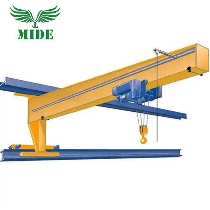
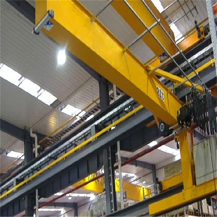
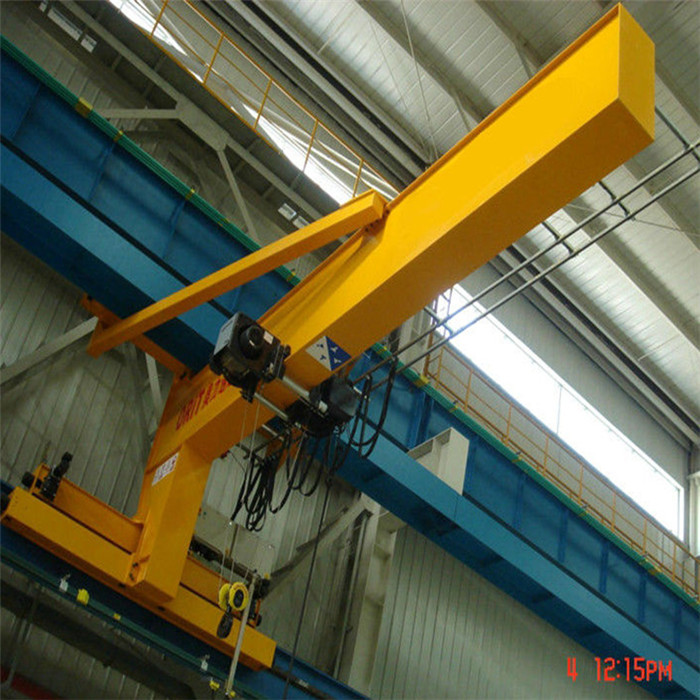
Wall Travelling Jib Crane a new suspends and transport equipment based on wall/column mounted jib cranes. Wall travelling slewing Jib Crane track is fixed concrete column in the factory workshop it can move in longitudinal way while Electric Hoist can finish transverse movement along horizontal vertical direction. This type of wall travelling jib crane machine expands the scope of working and uses the space of factory building efficiently, so will take a better use effect.
Jib Crane Design Calculation refers to a jib crane mounted on the wall and travels along the 2 rails fixed on only one side of the wall or steel structure.
The hoist mechanism is the same or similar to that of Floor Mounted Jib Crane. The biggest advantage of wall raveling jib crane is that it needs no floor space and girder or beams like Bridge Crane, thus saving workshop space.
Features
1. It is widely used in workshop, storage, warehouse, yard, fabrication shops, machine shops, assembly floors, loading/unloading area, indoor/outdoor operation and some other fixed place.
2. It is especially used for lifting in short-distance or serried place.

Specification of wall traveling jib crane
Type
BZ0.5
BZ1
BZ2
BZ3
BZ5
Lift Capacity (t)
0.5
1
2
3
5
Max. Lift Height(m)
3
3
3
4
4
Slew Angle(0)
360
360
360
360
360
Lift Speed (m/min)
Normal
8
8
8
8
8
Slow
0.8
0.8
0.8
0.8
0.8
Level Travel Speed (m/min)
20
20
20
20
20
Slew Angular Speed (r/min)
1
0.75
0.7
0.9
0.6


Advantage
Installation with high strength bolt connection;
Convenient in operation,safe and turn to flexible;
Low noise,commodious cabin and good looking;
High quality and efficiency, competitive price;
Reasonable and simple whole structure,Light self-weight, conform to the state standards;
Inexpensive handling systems doesn't require modification of the building structure around.

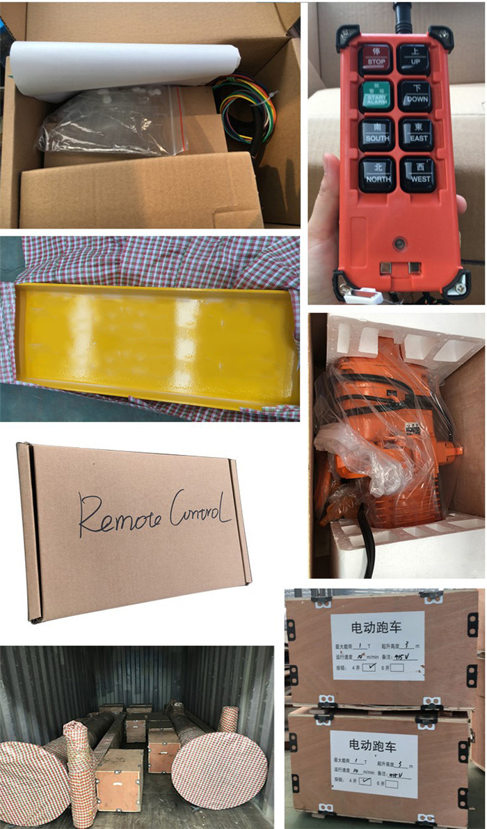
Our packing information

Wall Travelling Jib Crane
Wall Travelling Jib Crane,Wall Crane,Wall Jib Crane,Wall Travelling Crane
Jiangxi Mide Industrial Co., Ltd. , https://www.midecrane.com