Application of Acrel-6000 Electrical Fire Monitoring System in Harbin Medical University First Hospital
Ankerui Qingqing
Jiangsu Ankerui Electric Appliance Manufacturing Co., Ltd., Jiangyin , Jiangsu 214405 , China
Abstract: This article briefly describes the composition principle of electrical fire monitoring system , and analyzes the design basis and related specifications of electrical fire monitoring system in application . Finally, through the example of Ankerui's residual current electrical fire monitoring system in Harbin Qunli Medical University Hospital, the realization of the function of the electrical fire monitoring system and its significance were expounded.
Keywords: electrical fire; monitoring system; Acrel-6000/B; hospital;
0 Overview
First Affiliated Hospital of Harbin Medical University was founded in 1949, after over 60 years of development, from a 230-bed, small hospitals 395 employees, developed into a set of medical, teaching, scientific research as one of the large general hospital.
The hospital is the largest medical center in Heilongjiang Province, with complete medical specialties and strong technical force. The hospital has an outpatient department, an inpatient office, an emergency emergency center, and a remote consultation center. There are 93 clinical departments, 54 medical technology departments, 5,111 employees, and 908 professional or higher professional titles , with open beds. 4,398 . In 2012 , there were 1.988 million emergency and emergency visits, and 72,500 hospitalizations . The hospital also assumes the tasks of health care and diagnosis and treatment for the deputy provincial and above leaders and important foreign guests. The project is mainly responsible for monitoring the leakage status of the site distribution in the low-voltage distribution cabinets in the distribution room, and promptly reminding the duty-control personnel in the control room to prevent the occurrence of electrical fire.
On the site of Harbin Qunli Medical University, 56 ARCM200 residual current meters were installed in the distribution room. The field instrument is connected to the control center of the Acrel-6000/B wall-mounted electrical fire monitoring system via a bus.
1 Reference standard
In recent years, the state has successively formulated or revised a number of relevant standards and regulations to strengthen the prevention of electrical fires in order to increase the intensity of prevention and control of electrical fires. There are:
1.1. GB50045-95 (2005 edition) " High-rise Civil Building Design Fire Protection Code ", which provisions in the provisions of 9.5.1: high-rise buildings in the fire risk, personnel intensive and other places should be set up a leakage fire alarm system.
1.2. GB50016-2006 “Specifications for Fire Protection in Building Design†states in Clause 11.2.7 that the following places should be equipped with residual current action electrical fire monitoring systems. These venues include various types of theaters , halls, warehouses , residential quarters , hospitals , shops , schools, and so on.
1.3. The relevant provisions of the national standard “Building electrical fire prevention requirements and detection methods†also explicitly require that “the residual current protection device that automatically cuts off the power supply or alarm should be installed at the power input endâ€.
1.4. Electrical fire monitoring system products should meet: GB14287.1-2005 "Electrical fire monitoring equipment", GB14287.2-2005 "residual current electrical fire monitoring detector", GB14287.3-2005 "temperature-type electrical fire monitoring and detection Device
1.5. The installation and operation of electrical fire monitoring system shall meet GB13955-2005 "Installation and Operation of Residual Current Operation Protection Device"
1.6. The power supply of the electrical fire monitoring system shall meet the requirements of GB50052 "Design Specification for Power Supply and Distribution System"
1.7. The design of electrical fire monitoring system should meet the requirements of "Design Method for Electrical Fire Monitoring System" (Interim Provisions)
2 system components
The electrical fire project of Harbin Qunli Medical University Hospital consists of electrical fire monitoring background, electrical fire detectors and leakage current transformers.
The project communication bus accesses two communication buses. After the buses are handed in series in the power distribution room, they are connected to the wall-mounted background to form the major artery of the electrical fire system. The leakage current transformer in the box is connected to the leakage detector through the current line, and the leakage detector shows leakage in real time. The above constitutes a set of stable, accurate and reliable electrical fire monitoring systems. The system network is divided into three layers:
1) Station control management
        Station management The management personnel of the electrical fire monitoring system are the direct windows of human-computer interaction and the top part of the system. Mainly by the system software and necessary hardware devices, such as touch screen, UPS power supply and other components. The monitoring system software calculates, analyzes, and processes various types of data on the site, and responds to the on-site operations by means of graphics, digital display, sound, and indicator lights.
       Monitoring host: used for data acquisition, processing and data forwarding. Provides data interfaces within or outside the system for system management, maintenance, and analysis.
UPS: Ensure the normal power supply of the computer monitoring system. When the power supply problem occurs in the entire system, ensure the normal operation of the station control and management equipment.
The background monitoring equipment is set in the control room.
2) Network communication layer
      Communication medium: The system mainly adopts shielded twisted pair, uses RS485 interface, MODBUS communication protocol to achieve real-time communication between the field device and the host computer.
3) Field device layer
The system topology is as follows: 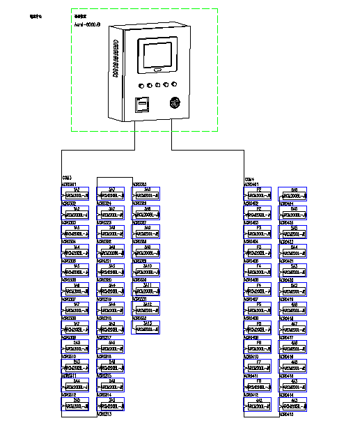 Â
Â
3, electrical fire equipment
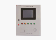
3.1, Acrel-6000 electrical fire monitoring background:
The main technical parameters
power supply:
1 rated working voltage AC220V (-15% ~ +10%)
2 Standby power supply: When the main power supply is under voltage or power failure, maintain the monitoring equipment working time ≥ 4 hours
Work system:
24-hour work
communication method:
RS485 bus communication, Modbus-RTU communication protocol, transmission distance 1km, can extend communication transmission distance through repeater
Monitoring capacity:
1 Monitoring equipment can monitor up to 200 monitoring units (detectors)
2 can be connected with ARCM series monitoring detector
Monitoring alarm items:
1 Residual current fault (leakage): Fault cell attributes (position, type)
2 Temperature alarm (over temperature): Fault cell attributes (part, type)
3 Current fault (overcurrent): Fault cell attributes (part, type)
Monitoring alarm response time: ≤30s
Monitoring alarm sound pressure level (A weighting): ≥70dB/1m
Monitoring alarm light display: red LED indicator, red light alarm signal should be maintained until manual reset
Monitoring alarm sound signal: Can be eliminated manually, when it is alarm signal input again, it can start again
Fault alarm item:
1 An open circuit or short circuit occurred in the communication cable between the monitoring equipment and the detector
2 Monitoring equipment main power supply undervoltage or power failure
3 An open circuit or short circuit occurred in the connection between the battery charger and the battery
Fault alarm response time: ≤100s
Monitoring alarm sound pressure level (A weighting): ≥70dB/1m
Monitoring alarm light display: yellow LED indicator, yellow light alarm signal should be maintained until troubleshooting
Fault alarm sound signal: Can be eliminated manually, when it is alarm signal input again, it can start again
During faults, normal operation of non-failed circuits is not affected
Control output:
Alarm control output: 1 set of normally open passive contacts, capacity: AC250V 3A or DC30V 3A
Self-inspection project:
1 Indicator check: alarm, fault, operation, main power, standby power indicator
2 display check
3 audio device inspection
Self-check time ≤60s
record:
1 Record content: record type, occurrence time, detector number, area, fault description, no less than 20,000 records can be stored
2 record query: according to the record of the date, type and other conditions
Operation rating:
1 daily shift: real-time status monitoring, event record query
2 monitoring operation level: real-time status monitoring, event record query, remote reset of the detector, device self-test
3 System management level: real-time status monitoring, event record query, remote reset of detector, device self-check, system parameter query of monitoring equipment, individual detection of each module of monitoring equipment, operator addition and deletion
Use environmental conditions:
1 Workplace: fire control room, manned power distribution (distribution room), on-call room walls
2 working environment temperature: 0 °C ~ 40 °C
3 working environment relative humidity: 5% to 95% RH
4 Altitude: ≤2500m
3.2, ARCM200L series instruments
The ARCM200L residual current electrical fire monitoring detector is designed for TT and TN systems up to 0.4kV. It monitors and manages the fire hazard parameters such as residual current, wire temperature, overcurrent, and overvoltage in the distribution circuit. This prevents the occurrence of electrical fires and enables real-time monitoring of multiple power parameters to provide accurate data for energy management. Products using advanced microcontroller technology, high degree of integration, compact size, easy installation, intelligent, digital, network in one, is the building electrical fire prevention and control, insulation insulation system, such as the ideal choice. The product complies with the standard requirements of GB14287.2-2005 "Electrical fire monitoring system Part 2: Residual current electrical fire monitoring detector".
4 system function
4.1. Monitoring alarm function:
The monitoring equipment can receive the leakage and temperature information of multiple detectors. When the alarm sounds, an audible and visual alarm signal is emitted. At the same time, the red “alarm†indicator light on the equipment is on. The display screen indicates the alarm location and type of alarm, and the alarm time is recorded. The sound and light alarm is maintained. Until the display resets the detector remotely. The audible alarm signal can also be manually cancelled using the display “Mute†button.
4.2. Fault alarm function
Communication failure alarm: When a communication failure occurs between the monitoring device and any connected detector, the corresponding detector in the monitoring screen displays a fault prompt, and the yellow “fault†indicator on the device lights up, and a fault alarm sounds. .
Power failure alarm: When the main power supply or standby power supply fails, the monitoring device also emits an audible and visual alarm signal and displays the fault information. You can enter the corresponding interface to check the detailed information and cancel the alarm sound.
4.3. Self-check function
Check if all status indicators, display screens, and speakers in the device are normal.
4.4. Alarm record storage query function
When leakage, over temperature alarm, or communication or power failure occurs, the alarm location, fault information, alarm time, and other information are stored in the database. When the alarm is removed and the fault is eliminated, it is also recorded. Historical data provides a variety of convenient and fast methods for searching.
4.5. Power Function
When the main power supply has a power failure or undervoltage, the monitoring device can automatically switch to the standby power supply. When the main power supply resumes normal power supply, it automatically switches back to the main power supply, ensuring continuous and smooth operation of the monitoring device during the switchover process.
4.6. Detector Control Functions
By monitoring the software operation, remote reset control can be performed on all detectors connected to the device.
4.7. Authority Control Function
In order to ensure the safe operation of the monitoring system, the monitoring device software operating authority is divided into three levels, and different levels of operators have different operating rights.
5 Concluding remarks
Harbin Qunli Medical University Hospital electrical fire monitoring system consists of the electrical fire monitoring device Acrel-6000/B, leakage fire detector leakage fire detector ARCM200L. Acrel-6000 electrical fire monitoring system is an independent research and development by the company to receive the residual current electrical fire detectors and other field equipment signals to achieve the alarm, monitoring, control and management of the protected electrical circuit running on the computer's industrial level Hardware/software system. This system is applied to fire control centers in large shopping malls, living quarters, production bases, office buildings, shopping malls and hotels, and remotely measures, remotely adjusts, remotely controls, and remotely detects the detectors scattered in buildings to facilitate monitoring and management. The system uses a standard Modbus field bus to connect detectors with communication functions. When the detected parameters in the field protection circuit exceed the alarm setting value, it can send alarm signals, control signals, can indicate alarm locations and save alarms. information. The on-site meter is connected to the control center of the Acrel-6000/B wall-mounted electrical fire monitoring system via bus. This system has the advantages of convenient installation and transportation, high cost performance, and easy maintenance.
references
[1]. Ren Chengcheng, Zhou Zhong, Principles and Application Guide for Digital Power Meters [M]. Beijing, China Electric Power Press, 2007. 4
[2] .Zhou Zhong . Application of Electric Power Meters in Energy Metering of Large-scale Public Buildings [J]. Modern Building Electric 2010. 6
NIKKO Starter: S6D95, S4D95, 6D155, S6D102, DA220, S6D105
POINTS TO ATTENTION:
1- Keep a careful check on gear ring before installation, replace one if damages.
2-Installed surface of both motor and generator should be kept clean, Make sure the strength to the bolts.
3- Clean each connection port, Strictly observed the sketch, Make sure of firm connection and tight electric conduction.
4- Check if the key could be automatic
NIKKO Starter
NIKKO Starter, NIKKO Starter Motor, NIKKO Starter Parts, NIKKO Auto Parts
NINGBO ZHONGWANG AUTO FITTINGS CO.,LTD , http://www.autostarter-alternator.com